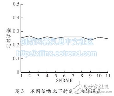
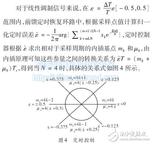
Abstract: This paper studies the timing synchronization algorithm based on digital filtering square for high-speed burst communication. Through the parallel structure implementation of the timing error estimation module of the timing synchronization loop in high-speed data transmission communication, the system's clock requirement is greatly reduced, and it is easier to implement; the timing control part mentioned in the paper is compared with other documents. The method was compared to show that the method used can achieve better results. Finally, the Matlab simulation and hardware implementation show that the loop can achieve high-speed data transmission timing synchronization in both burst and non-burst situations. At present, digital communication systems are developing in the direction of high speed and full digitalization. In the all-digital receiver timing synchronization, there are mainly two key points: timing error estimation and timing control. In the traditional timing synchronization method, the local sampling clock is generally directly adjusted to achieve the best sampling effect. In the all-digital receiver, the local sampling clock is unchanged, and the resampling clock is generated by calculating the timing error control to achieve optimal sampling. A method of achieving timing synchronization by generating a resampling clock is commonly used in the Gardner algorithm and the digital filtering method. Both of them belong to the interpolation method in timing synchronization, which is insensitive to the carrier signal and can be synchronized before the carrier. The difference is that Gardner belongs to the feedback type, and the digital filtering method belongs to the feedforward type, so the synchronization time of the latter is shorter. It is suitable for processing burst signals and is therefore widely used in all digital receivers with sudden situations. The digital filtering flat method is suitable for the research project, and it can process the timing synchronization of MPSK and MQAM modulated signals in the case of sudden bursts, and in the case of high-speed communication, by implementing the parallel structure of the timing error estimation module of the algorithm, it can be greatly reduced. For the requirements of the clock, it is necessary and meaningful to study the digital filtering method. For a general linear modulation signal, where cn is the transmitted symbol data; g(t): gT(t) & TImes; gR(t) is the system impulse response; gT(t) is the impulse response of the transmitter shaping filter ;gR(t) is the impulse response of the matched-end matched filter; T is the symbol period; s(t) is the slow-changing sampling time error; B(t) is the carrier phase difference, where the carrier phase difference is not considered, ie B(t) ) = 0, n(t) is Gaussian noise, n(t) ~ N(0, 2δ2), and the variance of the in-phase component and the quadrature component are both δ2. The received signal r(t) is sampled at a sampling rate of N/T. Then, the sampled signal is modulo squared to obtain an xk sample signal, and the sample signal includes a spectral component having a frequency of 1/T, and the spectral component includes timing error information. By extracting the Fourier coefficients of each data segment whose length is LN (ie, LN sample data; L represents the number of symbols of one operation; N represents the number of samples per symbol; generally takes N=4), the coefficient is extracted. for According to equation (3), when N=4, the timing error estimation implementation block diagram obtained by the formula transformation is shown in Fig. 1. After matching filtering, a bandpass filter with a center frequency of 1/2T and a bandwidth of α/T is added to filter out-of-band noise, and a Kalman filter is added after the error is found. The result is smoothed. For high-speed data transmission, at the front end of the timing synchronization, the ADC sampling adopts a parallel structure, that is, the ADC performs 4 times sampling by the parallel time interleaving sampling method. Then, the matched filter is designed as a parallel transposition type FIR, and parallel output is performed. The output result is again used in parallel structure, and image(x) and real(x) in equation (5) are respectively obtained, and the parallel structure is as shown in FIG. 2 . The preset timing error is 1/4, and the accuracy of the timing error estimation is verified under different input signal-to-noise ratios, as shown in FIG. The timing error parallel algorithm structure is able to correctly estimate the timing error. In the timing control section, the literature mentions the same control methods as in the Gardner algorithm, namely loop filtering and NCO control. Here, another timing control method is used in the paper to obtain a better effect. In the timing control part, the timing estimation algorithm is used to estimate the error value to control the integer interval mk and the fractional interval μk used to generate the interpolation. Gain Chip,Gain Chip Laser,Narrow Linewidth Laser Diode ,Single Spatial Mode Laser Diodes AcePhotonics Co.,Ltd. , https://www.acephotonics.com


