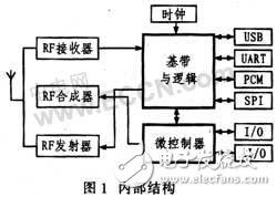
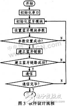
Bluetooth is one of the most promising technologies in the field of wireless communication, and it is also the only leading and only verified small-range wireless transmission technology, which is widely used. The Bluetooth device mainly has a two-chip method of baseband processing and radio frequency separation and a single-chip method of combining the two, and the latter has become a future development trend by reducing the size, reducing the cost, and simplifying the design of various Bluetooth devices. Compared with the products of TI and Broadcom, CSR's BlueCore4-ROM CSP has high integration, reduces power consumption and software footprint, expands capacity, and improves data transmission rate. It is currently a widely used Bluetooth device. one. 2.1 main characteristics BlueCore4-ROM CSP device features: operating voltage range 2.7 ~ 3.6 V, working frequency band 2.40 ~ 2.48 GHz; 8 Mbit Flash memory interface, 48 Kbit RAM on-chip; Bluetooth software protocol CSR or BGA with small space, support 802.11, Fully compatible with the Blue 2.0 specification; USB2.0 and UART host interface, PCM audio interface; support data and voice transmission, 2 levels of power output, up to 3 M modulation mode, suitable for mobile phones or PDA applications. 2.2 Internal structure Figure 1 shows the internal structure of a Bluecore4-ROM CSP device. It consists of a high frequency component plus a baseband controller. The high-frequency part adopts the universal TX/RX terminal, which simplifies the external matching circuit and eliminates the external antenna switch. It mainly consists of RF receiver, RF transmitter and frequency synthesizer. Among them, the RF receiver mainly includes a low noise amplifier LNA and an analog to digital converter ADC. A zero-IF structure is used and the channel filter is integrated. The low-noise amplifier LNA can be configured in two modes, one for the first-generation Bluetooth system and the second for the second generation. The analog-to-digital converter ADC is used to implement fast and automatic automatic gain control (AGC). It samples the received signal amplitude indication voltage RSSI, so that the pre-LNA guarantees that the input signal of the first mixer is within the effective range according to the standard RSSI, which improves the dynamic range and environmental interference of the receiver, making it complete. Channel filter. The RF transmitter mainly includes an IO modulator, a power amplifier, and an 8-bit digital-to-analog converter with a direct IQ modulator embedded in it, supporting DQPSK (2 Mb/s) and 8DPSK (3 Mb/s) modulation. The amplifier has a maximum power amplification of +6 dBm, which eliminates the need for an external RF power amplifier and transceiving switch in Class 2 and Class 3 transmission applications, and supports external amplifiers for Level 1 transmission, via an internal 8-bit digital-to-analog converter. Power Control. The frequency synthesizer uses a complete built-in synthesizer, eliminating the need for an external VCO (voltage controlled oscillator) and loop filter. The baseband part is mainly composed of a memory management unit, a trigger mode controller and a DSP, 48 KB of RAM, 4 MB of ROM and various interfaces. The memory management unit uses dynamic management to make the RAM work effectively. The trigger mode controller can reduce the interference caused by the processor during transmission and reception. There are special logic circuits in the DSP chip to perform front-end error correction, cyclic redundancy check, encryption, data erasure, audio conversion and other operations. The micro-control circuit consists of a 16-bit microcontroller, interrupt controller and burst clock to run the Bluetooth software package and control the main interface. 2.3 main pin description RF-A, RE-B are connected to the peripheral antenna matching circuit. XTAL-IN, XATL-OUT: The local oscillator and internal data clock are derived from the external crystal, and the frequency is available in a variety of options. The system uses a 26 MHz crystal. UART serial port: This device special serial port can communicate with other interfaces complying with RS232 standard. The serial port has UABT-TX, UART-RX, UART-RTS, UART-CTS4 signal lines. When the interface is connected to other devices, UART-TX and UART-RX exchange data between the two devices, and UART-RTS and UART-CTS can be used for control. PCM: Pulse code modulation is the standard for digital audio signals in digital communication channels. The device supports continuous transmission and reception of PCM data through hardware. I/O port: 13 I/O lines, PIO[0] for RXEN; PIO[1] for TXEN; all I/O ports can be configured for interrupt or wake-up. 3.1 hardware circuit design The Bluetooth system is based on the Spreadtrum SC6600D mobile phone baseband device and consists of the BlueCore4-ROM CSP and WM8731 audio codec. Since a separate audio codec device is used, only a few pins and a part of the port of the BlueCore4-ROM CSP device are used, so the circuit design is easy to implement and the flow is simple, and FIG. 2 shows the hardware connection circuit. The working principle is that the baseband device is controlled by software to issue a reset signal according to communication requirements. When powering up, the serial port 1 of the baseband device is first initialized to the Bluetooth device. When Bluetooth transmission is required, its main transmission and processing is the MP3 from the baseband device and the voice signal from the other party. First, the MIMIN pin of the WM8731 is used to receive the analog audio output signal from the AUXSPN/HEAD-R pin of the mobile phone baseband device SC6600D. The signal is transmitted to the handset or speaker when the Bluetooth is not activated. After being processed by A/D conversion, encoding, etc. in the WM8731, it is transmitted from the PCM interface to the BlueCore4-ROM CSP, and then modulated, amplified, etc., and then transmitted to the antenna. The antenna is transmitted to the Bluetooth headset for reception. When receiving, the main transmission and processing is the voice signal transmitted by the Bluetooth headset. After receiving the high-frequency signal sent by the Bluetooth headset, the Bluetooth antenna transmits it to the BlueCore4-ROM CSP, and after filtering, demodulating and the like, transmits the WM8731 via the PCM interface. Decoding and D/A conversion are performed, and then sent to the AUXMICP and AUXM-ICN pins of the baseband device through a differential circuit for further processing, and finally transmitted to the other party by the mobile phone. Mobile Bluetooth can also transfer files. When transferring files, the BlueCore4-ROM CSP transmits the received data to the serial port 1 of the baseband device through the serial port, and stores the data in the SD card of the mobile phone. The file in the SD card of the mobile phone can also be transmitted to the external Bluetooth through the path. Receiving device. 3.2 system software design The Bluetooth software architecture standard includes two major parts: Core (Core) and Profile (Application Protocol Stack). The former is the core of the Bluetooth protocol, which mainly defines the technical details of Bluetooth; the latter defines the corresponding implementation protocol stack, which lays the foundation for global compatibility. The Bluetooth standard mainly defines the underlying protocol and also defines some high-level protocols and related interfaces. The specific protocol is divided into 4 layers: 1 core protocol namely Bluetooth connection management protocol LMP, Bluetooth logical link control and adaptation protocol L2CAP, service detection protocol SDP); 2 Bluetooth cable replacement protocol RFCOMM; 3 telephone transmission control protocol TCBBIN/AT; 4 Some high-level protocols related to Internet use. That is, PUDP/TCP/IP, OBEX/vCard/vCal, IrMC, E-mail, WAP, and WAE. The device's software is mainly divided into standard Bluetooth HCI package and Bluetooth embedded host software (BCHS); supports Bluetooth v2.0 + EDR protocol specification, its Bluetooth process and application can be on-chip RISC microprocessor and off-chip master The processor runs between the two. Figure 3 shows the software design flow chart. A method to realize the Bluetooth function of mobile phone is studied. For the convenience of software programming and easy implementation, the WM8731 audio codec is designed and reprocessed by collecting the analog signal of the mobile phone, so that there is some duplication in signal processing. If you can directly lift the digital signal from the mobile phone baseband device to the Bluetooth device, you can save the WM8731 audio codec and reduce the cost. This will be a research direction in the future.
A TPU Screen Protector made of the super toughness of the honeycomb structure. Its unique ultra-soft properties allow it to cover the most complex curves and contours in a device.
Srceen Protector For Xiaomi,Hydrogel Screen Protector For Xiaomi,TPU Screen Protector For Xiaomi,Hydrogel Film for Xiaomi Shenzhen Jianjiantong Technology Co., Ltd. , https://www.jjtbackskin.com

The self-healing design of the Hydrogel Screen Protector can protect the display screen of the device from damage, leave no air bubbles, and maintain the sensitivity of the touch screen. Advanced anti-fingerprint and dust- and oleophobic overlays keep your screen smudge- and dirt-free. This overlay is also important in providing maximum touch sensitivity for improved high-speed glide and optimal touch response.
The optical transparency of the Hydrogel Film is more than 90%, showing you the most original screen color and bringing the most realistic visual experience.
If you want to know more about the product information of the Hydrogel Screen Protector for Xiaomi, please click the product details to view the parameters, model, picture, price and other information of the Xiaomi Screen Protector.
Whether you are a group or an individual, we will do our best to provide you with accurate and comprehensive information about Hydrogel Screen Protectors!
1 Introduction