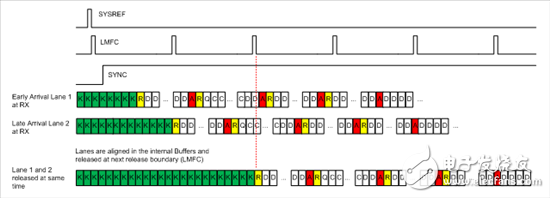
The three states in the JESD204B protocol are important for building valid data links between TX and RX of the link: Code Group Synchronization (CGS), Initial Channel Alignment Sequence (ILAS), and user data. Today I will explore the signaling techniques that are inevitable between TX and RX, and the necessary steps to build an effective link. Figure 1 - Signal Connections for the JESD204B TX to RX Link The signal from TX (tx_dataout) to RX is the serial deserializer channel signal containing the data link. These signals do not require offset alignment. The signal from RX back to TX is the SYNCn request signal. The clock chip is typically the LMK04828 ultra-low jitter synthesizer and jitter cleaner, which provides a device clock for txlink_clk and rxlink_clk. In addition, it provides SYSREF for synchronizing the TX and RX time domains. The transmitter and complementary receiver contain 8b/10b encoding, data link layer, scrambler and transport layer. We assume that both the transmitter and receiver use the same LMFS configuration and PLL settings. To verify the signal as it passes through the various states of the JESD204B protocol, use the signal analysis tools provided by the FPGA vendor. The first step in building a JESD204B link is that RX signals TX Start Code Group Synchronization (CGS): a.) RX lowers the SYNC signal for TX and requests execution of CGS. b.) The TX response will be to start sending K28.5 characters (0xBC hex before 8b/10b encoding). c.) After RX receives and decodes at least 4 K28.5 characters, it raises the SYNC signal and causes TX to start transmitting the ILAS sequence. Figure 2 – a) SYNC low signal request from RX to TX; b) TX responds with K28.5 (0xBC octet); c) SYNC is raised after RX receives K28.5 character, making TX Start sending ILAS The next step is the initial channel alignment sequence (ILAS): d.) Once SYNC is raised, TX will transmit the ILAS signal on each channel at the rising edge of the local multiframe clock (LMFC, LMFC not shown). All channels will be aligned from the source to the LMFC edge. e.) ILAS always contains 4 multi-frame data. Each multiframe data begins with a K28.0 character and ends with a K28.3 character. The link configuration data is transmitted through the second multiframe data at the beginning of the 3rd octet. Figure 3 – d) SYNC is raised by RX to tell TX to start ILAS; e) send ILAS over all channels f.) Figure 4 summarizes the structure of the ILAS multi-frame data, which is confirmed in the ILAS octet data stream sent by the TX. The K28.0=R and K28.3=A characters can be used to align all channels in a multipoint link. Figure 4. ILAS structure After completing ILAS, TX will send valid user data over the serial channel. g.) Within RX, each channel stores the last A character of the ILAS sequence and any subsequent user data in the elastic buffer of each channel. The release point of the user data in the elastic buffer is usually the next LMFC rising edge after the last A character in each channel's elastic buffer is detected. The received user data is just like on the TX side, and the serial bits will need to be rearranged through the back of the transport layer into meaningful parallel samples. h.) This channel alignment feature ensures that all data from each channel is alignable. In addition, it can withstand any channel offset caused by physical layout. This is one of the important features used in the process of implementing certain delays (which I will cover in a future blog). Stainless Steel Grinding Rod, 304 Stainless Steel Round Bar, Stainless Steel Flat Bar, Stainless Steel Threaded Rod ShenZhen Haofa Metal Precision Parts Technology Co., Ltd. , https://www.haofametal.com


