Circuit principle: This article refers to the address: http:// 4 in 1 magsafe wireless charging Guangzhou Lufeng Electronic Technology Co. , Ltd. , https://www.lufengelectronics.com
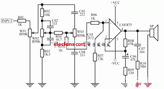
The LM1875 power amplifier board consists of an attenuated tone control circuit controlled by a high and low sound, and a LM1875 amplifier circuit and a Power Supply circuit. The tone part adopts an attenuated tone circuit controlled by high and low sounds, among which R02, R03, C02 C01, W02 form the bass control circuit; C03, C04, W03 form the treble control circuit; R04 is the isolation resistor, W01 is the volume controller, adjust the volume of the amplifier, C05 is the DC blocking capacitor, to prevent the LM1875 DC potential pair of the latter stage The influence of the pre-tone circuit. The amplifier circuit mainly adopts LM1875, which is composed of 1875, R08, R09, C066, etc. The amplification factor of the circuit is determined by the ratio of R08 and R09. C06 is used to stabilize the drift of the DC potential of the 4th pin of LM1875, but has a certain sound quality. The effect of C07, R10 is to prevent the amplifier from generating low frequency self-excitation. The load impedance of this amplifier is 4 → 16Ω. 
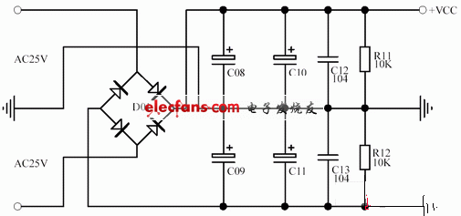
In order to ensure the sound quality of the power amplifier board, the output power of the power transformer should not be lower than 80W, the output voltage is 2*25V, the filter capacitor is connected in parallel with two 2200UF/25V electrolytic capacitors, and the positive and negative power supplies share four capacitors of 2200UF/25V. The monolithic capacitor of 104 is a high frequency filter capacitor that is good for the sound quality of the amplifier. 
Assembly and commissioning:
Tool preparation: 20W electric iron, preferably temperature-adjustable, if necessary, can contact the stationmaster; a universal meter, a needle-nosed pliers, a screwdriver, solder wire and pine perfume.
Prepare for welding: Weld the parts and weld small ones. Before welding LM1875, we must first fix the LM1875 with screws on the heat sink. Otherwise, the screws will be difficult to get in when the heat sink is installed last. The part of the LM1875 that is in contact with the heat sink must be coated with a small amount of thermal grease for heat dissipation. Attention must be paid to the quality of the welding when welding. For beginners, you can practice several times on the used circuit board and then formally solder.
Commissioning: This power amplifier board debugging is particularly simple. After soldering the electronic components on the circuit board, carefully check the board for soldering faults. Pay special attention to the electronic components with polarity, such as electrolytic capacitors, bridge rectifiers, once soldered. anti insurance that is burning yuan devices, please pay special attention. Connected to the transformer, the output of the amplifier is not connected to the speaker, but to the universal meter, preferably digital display, the multimeter is placed in the DC*2V file. On the power amplifier board, pay attention to observe the reading of the universal meter. Under normal circumstances, the reading should be within 30mV. Otherwise, the board should be powered off immediately. If the reading of the meter is within the normal range, it indicates that the function of the power amplifier board is basically normal. Finally, the speaker is connected, the music signal is input, the test machine is powered on, the volume potentiometer is rotated, the volume should be changed, and the high and low sound knobs are rotated. The pitch has changed.
Introduction to LM1875: 
LM1875 adopts TO-220 package structure, which is like a medium power tube. It has small size, simple peripheral circuit and large output power. The integrated circuit is internally provided with overload overheating and inductive load reverse potential safe working protection.
LM1875 main parameters:
Voltage range: 16 ~ 60V
Quiescent current: 50MmA
Output power: 25W
Harmonic distortion: <0.02%, when f=1kHz, RL=8Ω, P0=20W, rated gain: 26dB, when f=1kHz, working voltage: ±25V
Conversion rate: 18V/μS 