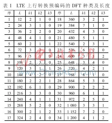
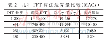
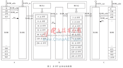
Abstract: On the basis of comparing existing FFT implementation methods, a design scheme of general FFT processor based on FPGA is proposed. This FFT implementation structure is dynamically configured into corresponding processors according to different input data lengths, and can support various FFT calculations with bases 2, 3, and 5, hardware resources are optimized, and processing speed and data accuracy meet SC in LTE system. -FDMA baseband signal generation requirements. The uplink transmission scheme selected by LTE is a new variable: SC-FDMA (single carrier-frequency division multiple access) has the advantage over traditional OFDMA that it has both a low peak-to-average power ratio (PAPR) for single carriers and multiple carriers Reliability. This is particularly important in the uplink. The lower PAPR can greatly improve the performance of the mobile terminal in terms of transmission efficiency, thus extending battery life. The baseband signal generation process representing the LTE physical uplink shared channel (PUSCH) is shown in Figure 1 [1]. The conversion precoding in Figure 1 is completed by a symmetrical form of DFT, and its type and conversion length L = 2k1 & TImes; 3k2 & TImes; 5k3 (L≤1 200) are shown in Table 1. Conversion precoding is to dynamically perform a DFT in Table 1 according to different input lengths L. Its main feature is that it contains many types of DFT and large scale, which brings challenges to hardware design. Most of the previous literatures focused on radix 2 or a single mixed radix FFT [6], but articles with multiple mixed radix FFTs as the core are still difficult to find. This paper proposes a conversion precoding solution based on FPGA. 1 Algorithm selection Cooley-Tukey algorithm and Good-Thomas algorithm are currently popular FFT algorithms, and their principles have been discussed in depth in [2], so I wo n’t repeat them here. (1) Cooley-Tukey algorithm has good modularity, and can realize in-situ calculation, and has regularity for the extraction of input data and rotation factor. A radix-3 FFT algorithm proposed in [3] is another expression of Cooley-Tukey algorithm applied in radix-3 FFT. An important fact that this algorithm is different from other FFT algorithms is that the factors can be selected arbitrarily, the versatility is strong, and all the arithmetic units are the same, which is easy to implement. (2) The Good-Thomas algorithm is only suitable for the case of factor prime. Since the calculation of the intermediate stage multiplication factor is avoided, the number of operations is much less than that of the Cooley-Tukey algorithm. The larger the number of FFT points, the more it can reflect its advantages in terms of saving resources. Reference [4] proposes a transmission precoding solution based on Cooley-Tukey algorithm. The advantages of this scheme are simple operation, module rules, and favorable programming; the disadvantage is that there are more multi-level rotation factor multiplications (up to a few hundred), and the hardware resources such as multipliers and memory are expensive, and the coefficient will be greatly increased. The workload of initialization. See Table 2 for a comparison of FFT calculations of several different lengths. The hybrid algorithm in Table 2 refers to the combination of Good-Thomas algorithm and Cooley-Tukey algorithm. It can be seen that the combination of the Good-Thomas algorithm and the Cooley-Tukey algorithm reduces the multiplication number of the interstage rotation factor compared with the literature [4], which can effectively reduce the amount of calculation. The reduction of these calculations plays a role in the realization of the entire system The crucial role, and the price it pays is only a slight increase in complexity. In summary, when implementing the hybrid FFT, the Good-Thomas algorithm is combined with the Cooley-Tukey algorithm, and the Good-Thomas algorithm is preferred, followed by the Cooley-Tukey algorithm. The system design will start from the Good-Thomas algorithm. 2 Overall structure design It can be seen from Table 1 that there are many types of FFT transforms to be performed by LTE uplink conversion precoding, but the architecture of each transform is similar, and is composed of common modules of radix-2 and non-radix-2 FFT. Modules with base 2 points of 4, 8, 16, 32, 64, 128, 256, modules with non-base 2 points of 3, 9, 15, 27, 45, 75, 81, 135, 225 and 243, As long as these common modules are extracted and carefully designed, and then called reasonably, this seemingly tedious work will be successfully completed. In the overall structure block diagram shown in Figure 2, modules A and C are data input and output modules respectively; module B is a data processing module whose main idea is dynamic configuration and multiplexing of public modules. The internal FFT module is separately generated in advance, MUX1, MUX2 is a selector, which dynamically configures different internal FFT modules to combine to form an outer FFT under different input points. In this way, the internal FFT module can achieve the purpose of multiplexing, which can greatly reduce the overall resource consumption and the processing speed. This is equivalent to performing each FFT separately. 3 hardware implementation In practical applications, FPGAs are generally required to complete fast and relatively fixed operations, and DSPs are used to complete tasks that are flexible and computationally intensive [7]. The Xilinx Virtex-5 SXT platform is optimized for DSP and memory-intensive applications with low-power serial connection. It has the characteristics of reconfigurable hardware structure, suitable for front-end digital signal processing with fixed algorithm structure and large amount of calculation. Unloading these functions in large quantities, freeing up DSP bandwidth to handle other functions, all of which make FPGAs show their unique advantages in the field of digital signal processing. 3.1 Address mapping The process of analyzing the working principle of the implementation process in the system shown in Figure 2 with 1 080 point FFT is shown in Figure 2. Because 1 080 = 8 & TImes; 135, and 8 and 135 are relatively prime, the outer layer uses Good-Thomas algorithm. Enter the address map: The use of FPGA embedded Block RAM can greatly save FPGA configurable logic function block (CLB) resources. Good-Thomas algorithm needs to sort the input and output data, the input and output processing method is the same, only the input processing is introduced here. At the input, in view of the characteristics of Block RAM, set up a ROM and RAM, as shown in block A of Figure 2. For FFT of different lengths, ROM is different, but RAM can be shared. The position number of the input data in RAM1 is stored in the ROM in advance. This position number is obtained by the formula (1). When the clock edge arrives, the position number stored in the ROM is read out sequentially, and this number is entered as the address of the RAM1 , You can store the input data to different locations in RAM1. This completes the sorting of the data at the same time as the data is entered, and it does both. 1 080 point FFT input and output terminal address index is shown in Figure 2, and its logical timing diagram is shown in Figure 3. In Fig. 3, RAM_in is input by bit splicing of test data xn_i and xn_r. 3.2 Internal FFT processing unit When performing the operations in module B of Figure 2, the internal FFT module is first generated separately. The FFT IP core provided by Xilinx is suitable for radix-2 point FFT transformation. The algorithm used is Cooley-Tukey algorithm, the transformation length is N = pow2 (m), m = 3 ~ 16, both the data sampling accuracy and the rotation factor accuracy It is 8 ~ 24, so the 8, 16, 32, 64, 128 and 256-point FFT of module B can be generated by IP core. Selecting "Pipelined, streaming I / O" to generate a base 2 point FFT module can reduce the overall processing time. The outer layer algorithm of 15, 45, 75, 135, 225 point FFT module is Good-Thomas algorithm, and the rest is implemented by Cooley-Tukey algorithm. Specific to 1 080 point FFT, the data in RAM1 is read out sequentially, and MUX1 chooses to perform 8-point FFT transformation. After completing the first level operation, the intermediate results obtained are sequentially stored in RAM2; then the intermediate results in RAM2 are taken out , MUX2 chooses to perform 135-point FFT transformation, operate a total of 8 times, complete the second-level operation, the results are stored in RAM1 in the order indicated by the ROM in module C; the final output of the contents of RAM1 is the result of 1 080-point FFT . 3.3 Multiplier design The quantization effect is a very important issue in the realization of digital signal processing technology, mainly including operation quantization effect, coefficient quantization effect, etc. The former has more influence than the latter [5]. Overflows may also occur during the operation, causing greater errors. The above problem puts forward requirements on the design of the multiplier. From the above, the base 2 FFT is generated by the IP core, so the multiplier design here is only valid for the non-base 2 FFT. Xilinx's XC5VSX95T has a total of 640 DSP48Es, and each DSP48E contains a 25 & TImes; 18 multiplier. When calling the multiplier IP, set the multiplier to the signed type with a width of 25 and 18 (rotation factor bit width is 18), output the intercepted result [41:17] total 25 bits, the input and output width of the multiplier is equal The result is scaled at the same time as the result is output, which is conducive to the modularization of the program, but the premise is to ensure that the data does not overflow. Because the input sample data width is only 16 bits, and the maximum length of the converted precoded input data is only 1 200 points, considering the rotation factor coefficient is less than 1, it can be concluded that the 25 bit bit width can make the multiplier result not overflow, and the operation accuracy can also be satisfied Claim. 4 Performance analysis The program is written in Verilog HDL hardware description language and compiled successfully in Xilinx's high-performance design and development tool ISE10.1i. When the FPGA chip is selected as XC5VSX95T, the maximum clock frequency is 105.6 MHz after logic optimization and synthesis in Synplify Pro 9.6.1, FFs consume 29 150/58 880, LUTs consume 37 625/58 880, multiplier Consume 414/640, Block Ram consumes 176/488, and all indicators meet the requirements. After successful layout and wiring, a real sinusoidal test signal is generated in Matlab, sampled and quantized into 1,200 points of data, and then input into Modelsim SE 6.1d for post-simulation of the program, and then the output result is sent back to Matlab, and the simulation diagram is shown in Figure 4. It can be seen from Figure 4 that the processed results of the FFT processor are basically consistent with the theoretical results calculated by Matlab, and the maximum absolute value of FFT is obtained at frequencies of 15 Hz and 335 Hz. The error between the two is precisely the quantization of digital signal processing Embodiment of the effect. Viewed as a whole, these errors are unavoidable and tolerable after the data is sampled, quantized, and truncated, so it can be judged that the test results meet the accuracy index. This article discusses the hardware and software implementation of multiple FFTs used in LTE uplink conversion precoding. Compared with various FFT processing alone or only using the Cooley-Tukey algorithm, this design cleverly combines the Good-Thomas algorithm with the Cooley-Tukey algorithm, which has great savings in hardware resources and cost consumption. Speed It can also meet the requirements, and this structure is easy to expand the function, only need to adjust the type and number of internal FFT units. The realization method of this large-scale mixed-base FFT has certain universality for the large-scale FFT on other occasions. Shenzhen ChengRong Technology Co.,Ltd. , https://www.nblaptopstandsupplier.com


