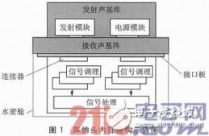
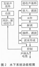
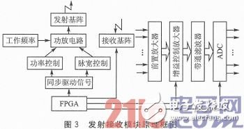
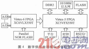
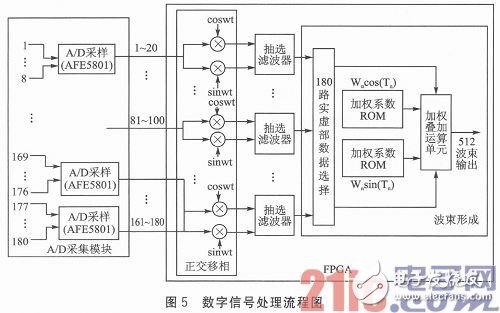
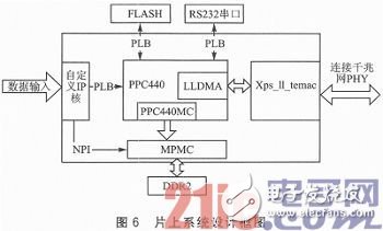
Abstract : A hardware circuit design scheme of multi-beam imaging sonar based on FPGA is presented. The specific circuit implementation of each subsystem in this scheme is introduced. The FPGA chip of Xilinx is used as the core device, according to the dry end PC. The issued control command realizes control of the 180-element transmitting and receiving circuit, completes digital beamforming, and transmits the beam data to the dry PC through the Gigabit network for display. The system circuit design is simple, with strong flexibility and scalability. The hardware architecture of the system is introduced in this paper. The hardware design of the front-end and digital signal processing modules of the multi-beam imaging sonar system is demonstrated. The actual test results show that the system can clearly image the underwater terrain features in real time, with a refresh rate of 15 frames/s. introduction Multi-beam imaging sonar utilizes digital imaging technology to form a two-dimensional two-dimensional acoustic image in the seabed detection range, which has high system stability and strong signal processing capability. However, due to the large amount of data calculation and the need for real-time imaging, the digital imaging system requires high performance. With the rapid development of field-programmable gate array (FPGA) devices for parallel processing, image sonars using large-scale FPGAs as core processors have improved overall system performance while simplifying overall system architecture. The imaging sonar circuit system is located inside a sealed watertight compartment, and is composed of a 180-channel transceiver module, a real-time signal processing module, a data transmission and control module, a power module, an interface board, and some connectors. The internal structure of the specific sonar head is shown in Fig. 1. The dark part of the figure is the sonar transmitting and receiving acoustic array. When the system works, the oscillating signal generated by the transmitting module is converted into a pulse sound wave by transmitting the sound matrix, and the signal is reflected at the bottom of the water, and the reflected sound wave signal is converted into an electrical signal by the receiving sound matrix, and enters the receiving circuit. The receiving sound array has 180 primitives, and the echo signals output by each primitive enter the receiving circuit through the interface board for signal conditioning and acquisition. The collected 180 digital signals are then input into the signal processing module, which performs a series of processing such as complex demodulation, sampling and digital filtering on the collected data to implement digital beamforming and control the final beam data transmitted by the Gigabit network transmission system. . At the same time, the dry-end PC sends control commands in real time to transmit and receive circuits and beam shapes. The process is controlled. The power module is responsible for powering the various sub-modules in the imaging sonar system. The functional block diagram of the system is shown in Figure 2. The performance of the transmit and receive circuits directly affects the quality of multi-beam sonar imaging. The block diagram of the transmitting and receiving module is shown in Figure 3. The power amplifier circuit generates an oscillating signal of different intensity and different pulse width under the action of the working frequency signal generated by the frequency synthesizer, the pulse width control circuit and the power control circuit, and the signal is loaded on the transmitting array and converted into a pulse wave. Launched. The receiving array synchronously converts the sonar echo into an electrical signal through the control signal of the FPGA, and sends it to the conditioning acquisition circuit at the front end of the receiver to perform preamplification of small signals, TVG/AGC amplification, filtering, and acquisition, etc., to generate 180 channels of digital signals. The FPGA controls the gain control amplification module and the ADC module according to instructions issued by the PC, and performs time gain amplification and automatic gain control on the signal. According to the design requirements, the digital signal processing and transmission module mainly implements beamforming of the echo data, and sends the beam data through the Gigabit network port and the control command of the PC end. The overall block diagram of the module circuit is shown in Figure 4. The signal conditioning acquisition circuit of the sonar receiving module simultaneously collects the echo signals of each receiving array element to generate 180 digital differential signals. In the digital signal processing module, the collected signals are sequentially subjected to complex demodulation, filter extraction, and beamforming, and finally 512 beam data are output. The specific signal processing flow is shown in Figure 5. This system uses Xilinx Virtex 6's XC6VLX550T chip as the core device for real-time data processing and beamforming. The amount of resources required by the actual algorithm and the number of resources of the XC6VLX550T are slightly - editor's note. The beam output by the digital signal processing module has a data transmission rate of 58.007 Mbps in the range of 100 m. The system uses a design margin of more than 2 times to realize the network transmission of the beam data through the Gigabit network. The design uses Xilinx's Vitex-5 FX70T FPGA as the platform. Based on the internal PowerPC440 hard processor of the chip, the VxWorks operating system is transplanted on the processor to complete the data transmission function of the data. The design block diagram of the system on chip is shown in Figure 6. Disposable Vape,Disposable Vape Pen,Disposable Vape Elf Bar Lux,Disposable Vape Pod Device Shenzhen Zpal Technology Co.,Ltd , https://www.zpal-vape.com