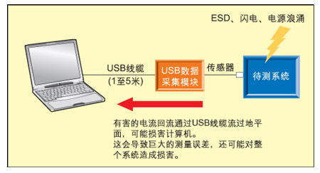
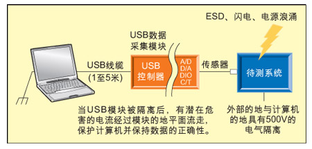
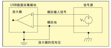
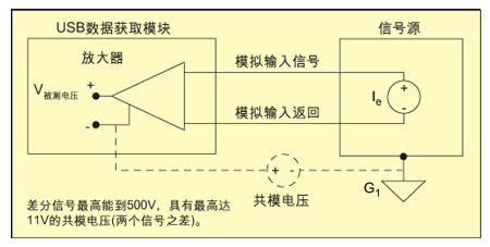
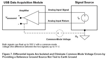
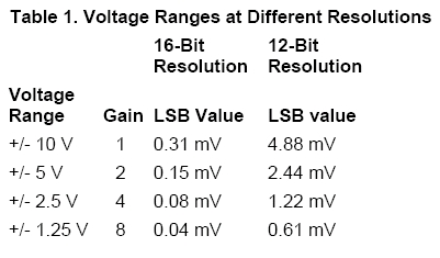
Advantages of using USB for testing and measurement USB has the following advantages, making it an easy choice for users to develop test and measurement measurement applications. True plug-and-play: Simply connect the data acquisition module to the PC's USB port using standard, low-cost cables. When the module is plugged in, the PC automatically recognizes the module and installs the necessary software to operate the module. This connection greatly reduces startup time. Instead of opening the PC chassis to add boards, configuring jumper switches and interrupt settings, searching for the correct device driver, or rebooting the system, simply connect the sensor to the module and forget about it. In a matter of minutes, you can continuously get any information you need, such as data, temperature, pressure, and sound. Less affected by PC noise: The USB data acquisition module provides performance advantages for noise-sensitive measurement applications. Because the USB cable is usually 1 to 5 meters in length, the I/O circuit is farther away from the computer's electromagnetic noise-filled motherboard and power supply, and closer to the sensor to be measured. Full-speed and high-speed transfer rates: Computers with a USB 1.1 port can input and output data from a USB data acquisition module at up to 12 Mbps. This full speed rate is useful for data flow applications and can support data acquisition rates up to 400KHz. For high-performance applications, you must ensure that your PC has a high-speed USB 2.0 port. With USB 2.0, data can be transmitted between PC and USB data acquisition modules at up to 480 Mbps. This increased bandwidth allows multiple I/O operations to be performed at the same time, each with traffic rates up to 500 kHz, similar to the PCI measurement system. Cost Savings: Many USB data acquisition modules include removable terminal modules or BNC connectors that are used to conveniently handle all user I/O connections. This design is not only easy to use, but it also saves money because you no longer need to purchase optional screw-fast terminal fittings. Portability: USB data acquisition modules are small and easy to carry, which allows users to bring even the most complex test and measurement applications out of the lab and into the field. Easy to expand: With a low cost expansion hub and USB cable, up to 127 data acquisition modules can be connected to one USB port. Hot-swappable: The USB data acquisition module can be installed or removed while the computer is running. Just plug in the device when it is used and pull out the device after completing the work. It is not necessary to shut down the computer. Because the USB module can count and recognize itself, when the module is plugged in, the device driver automatically loads; when the device is unplugged, the device driver automatically unloads. Simple power connection: The USB data acquisition module can be powered via the USB bus or simply connected to an external power source. The low-power module absorbs less than 100mA at 5V and is powered via a USB cable. The self-powered module draws up to 500mA at 5V and uses the module's own power supply. USB for potential hazards of test and measurement Although USB offers many advantages, not all USB data acquisition modules can be designed in the same way. Depending on the application, there may be potential hazards. The design of a USB module may have catastrophic consequences. Unlike a real ground system where the PCI board has a short distance to the PC backplane, the USB module has long distances (up to 5 meters) and active circuits at both ends of the cable. If the module is not designed properly, this can lead to system lock-up, unstable performance, and electromagnetic interference, which is a significant issue for noise-sensitive measurements. Before selecting the USB data acquisition module, consider the following questions for the target application: Is a data acquisition module susceptible to electrostatic discharge (ESD), lightning, or power surges from motors, switchgear, or other devices? Does the application involve voltages with different ground potentials? Will this module work in a good environment? If the answer to question 1 or 2 above is yes, you need to ensure that your system has quarantine measures. Isolation protects the PC from damage, and protects your data integrity by physically isolating electrical connections between circuits, that is, limiting potentially harmful voltages or currents through your system. Isolation can also be provided by adding signal conditioning accessories to the system, which can be prohibitively expensive, or the isolation of the USB data acquisition module can be chosen at the outset. Let's analyze these application environments more carefully and understand the role of isolation in each case. Figure 1: Typical application settings. Figure 2: An unisolated USB data acquisition module can damage the system and result in incorrect data during ESD, lightning, and power surges. Figure 3: Isolated USB data acquisition module application. Figure 4: Improper connection Single-ended input can damage your system and result in incorrect measurements. Figure 5: Correct single-ended input connection. Figure 6: Differential inputs are isolated, eliminating common-mode voltage errors by providing a reference ground source that is not connected to ground. Figure 7: Differential inputs are isolated, eliminating common-mode voltage errors by providing a reference ground source that is not connected to ground. Table 1: Voltage ranges with different resolutions. Case 1: ESD, Lightning, or Power Surge Figure 1 shows a typical application scenario where one sensor is measuring the voltage of the device under test. The sensor is connected to the USB data acquisition module at one end and to the PC at the other end. ESD, lightning, and power surges generate sudden transient overvoltages. Even a short time can damage the electronic components in the entire system. If the USB data acquisition module is not isolated (see Figure 2), the current generated by these events flows back through the system, eventually reaching the PC and potentially damaging the PC and other system components. Non-isolated modules provided by some data acquisition solution providers actually lock the entire system when there is an instantaneous overvoltage and have to restart the system. This behavior is unacceptable in measurement applications. In contrast, the isolated module (shown in Figure 3) protects the entire system by releasing harmful currents through the ground plane of the module. Even if the transient voltage introduced is not enough to damage the system, be careful that your data may contain large errors, especially at high resolution. For example, if you use a USB module with 16-bit resolution to measure signals in the ±10V voltage range, the LSB value is 0.31mV (see Table 1). If this module is not isolated and instantaneous voltages are present in the electrical system, the data may therefore deviate by hundreds of millivolts. Even in a static environment, your data may deviate by tens of millivolts. This is a huge mistake when measuring low-level signals. If high-precision, low-noise measurements are required, isolation is critical. All Data Translation USB modules, from the DT9801 Series to the DT9834 Series, provide electrical isolation up to 500V. Electrical isolation converts the energy in the input signal into an output signal that flows away on the ground plane of the module. As a result, your computer stays safe and measurement results are more accurate. Taking the DT9801 module as an example, it provides up to 500V electrical isolation by using the following components: Transformer: converts energy from a fast, no-delay clock signal; Optoisolator: converts energy from slower control signals with tens of millisecond delays; Differential capacitive coupling: Convert energy from a slow data path with a delay of 1 millisecond. Case 2: Different ground potentials The single-ended analog input is the non-isolated input of the reference ground. In an unisolated system, even digital I/O signals are connected to the same ground. If the system under test and the USB data acquisition module share the same ground (via the power system connected to the building), the difference between the two devices' ground potentials actually exists (over 100 mV). Fast switching current must flow to the PC along a 5-meter USB cable. Depending on how single-ended inputs are connected to the module, you may introduce ground loop error, which means that when signals and other ground potentials are added to USB cables up to 5 meters in length, not only highly inaccurate measurements are brought about. As a result, it may also damage the system under test. Figure 5 shows an example of an improper single-ended input connection. Figure 6 shows a better single-ended input connection scheme that reduces ground loop errors. For the most accurate measurement, a differential input (shown in Figure 7) can be used. Differential inputs are isolated inputs because the reference ground referenced by them is not connected to ground. As a result, they eliminate common-mode voltage errors that can occur when ground potential differences occur. Therefore, if you are measuring low-level signals, noise is a very important part of the measurement. Or if the common-mode voltage is present, make sure that the USB data acquisition module provides a differential input connection. All Data Translation USB modules, from the DT9801 Series to the DT9834 Series, provide up to 8 or 16 differential input connections to provide maximum ground loop protection. Case 3: Good circumstances In a good environment, the instantaneous electrical signal glitch and ground potential difference do not exist, so isolation is not required. In an unisolated system, the PC is directly connected to the ground system of the sensor, so as long as no noise or other errors are added to the voltage source, the measurement will be accurate. Although unsegregated solutions may be cheaper to purchase, test and measurement applications are rarely in good condition. So be careful, if you choose an unsegregated solution, it can lead to measurable back-end costs due to additional data due to inaccurate data or system failure. Elf Bar,Elf Bar With All The Flavors,Raspberry Elf Bar,Elf Bar 1500 Vape Shenzhen Zpal Technology Co.,Ltd , https://www.zpalvapes.com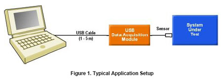
Due to the ease of use of USB, it has become one of the fastest growing buses in the computer and electronics industry today. For test and measurement applications, the USB data acquisition module has several significant advantages. But be wary, depending on the application, they may also contain some potential dangers, and even lead to disastrous consequences.