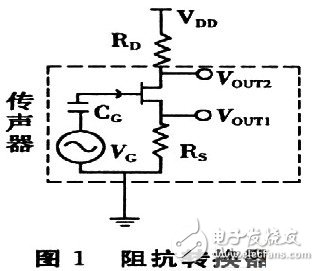
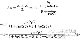
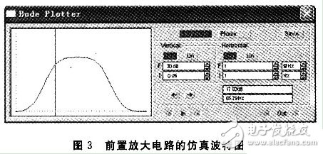
With the rapid development of China's communications industry, the demand for electret microphones is also growing. At present, some small electret microphones can integrate the FET into the microphone. However, due to the high price of high-end products, the accuracy and sensitivity of the low-end product microphone cannot be guaranteed, plus the traditional preamplifier volume. It is too big. Therefore, it is very important to design a preamplifier with the smallest possible size, low cost and excellent performance. 1 Overview of the principle of electret microphones A microphone is an electro-acoustic transducer that converts an acoustic signal into a corresponding electrical signal. The electret microphone is a new type of microphone made of electret material. It has the advantages of simple structure and high sensitivity, and is widely used in language pickup and acoustic signal detection. The interior of the electret microphone mainly includes two parts: acoustic and electrical conversion and impedance transformation. The acoustic-electric conversion part includes a diaphragm, a plate, and a gap. The key component of the acoustic-electrical conversion is the vibrating membrane, which is a very thin plastic diaphragm. On one side, a layer of pure gold film is evaporated, and then, after passing through the high-voltage electric field, the opposite sides are respectively charged with opposite charges, and the diaphragm is The steamed gold faces outward and communicates with the metal casing. The other side of the diaphragm is separated from the metal plate by a thin insulating collar so that a capacitance is formed between the vaporized gold film and the metal plate. When the sound is transmitted, the diaphragm vibrates with the movement of the sound wave, and the capacitance between the diaphragm and the fixed electrode also changes with the sound. Thereby, an alternating voltage signal which changes with the change of the sound wave is generated, thus completing the process of converting the sound into an electrical signal. The magnitude of the voltage change reflects the strength of the external sound pressure. This voltage change frequency reflects the frequency of the external sound. The capacitance between the diaphragm of the electret microphone and the plate is relatively small, generally several tens of pF. Therefore, the electrical signal output impedance is high and weak. Therefore, the output of the electret microphone cannot be directly connected to the audio amplifier. The field effect transistor has the characteristics of extremely high input impedance and low noise figure. Therefore, a junction field effect transistor with a very high input impedance is generally connected inside the microphone to amplify the voltage signal generated by the electret capacitor. At the same time, the signal is output at the source S or the drain G with a relatively low impedance to achieve impedance transformation, as shown in FIG. Figure 1 shows that UOUT1 or UOUT2 is the output signal of the microphone. Since UOUT1 is not affected by the power supply noise VDD and has strong resistance to power supply noise, UOUT1 is connected to the preamplifier for amplification. 2 Design analysis of preamplifier circuit The function of the preamplifier is to pre-amplify the signal output from the condenser head, and on the other hand to convert the high output impedance of the capacitor head into a low impedance output. The circuit of the small preamplifier mainly consists of two parts, one of which is an impedance conversion circuit composed of a field effect transistor, and the other part is an amplification circuit which will be analyzed in detail below. 2.1 Simplified model of the amplifying circuit The preamplifier circuit of the microphone is shown in Figure 2. In the figure, the op amp uses the MAX4465 microphone preamplifier from the US Maxim, and the MAX4465 is a 5-pin SC70 package with low cost and low power consumption. The simplified analysis and explanation of the principle of this circuit is given below. In order to facilitate the analysis of the circuit, let Z1=R1+1/(jωC1), Z2=R2//1/(jωC2)=R2/(1+jωR2C2), according to the characteristics of the virtual short and virtual break of the ideal op amp. , you can get the transfer function of the circuit as: It can be seen from equation (1). When ω→∞ or ω→0, the transfer function of the circuit is Au→1. 2.2 Estimation of mid-band passband gain In the frequency band of the speech signal (20 Hz to 20 kHz), select the appropriate R2 and C2 values ​​so that R2C2≈O, then 1+jωR2C2≈1, if 1+jωR1C1≈jωR1C1 is carried in the transfer function of (1) , can get Au≈1+R2/R1. If R2 = 10R1, then Au = 1 + R2 / R1 ≈ R2 / R1. 2.3 Estimation of the upper limit cutoff frequency When the frequency of the signal is high, that is, the value of ω is large in the passband, and R2=10R1, the formula (1) can be changed to: As can be seen from the above equation, ω = 1 / (R2C2), that is, f = 1 / (2πR2C2) is the upper limit cutoff frequency corresponding to the circuit. 2.4 Estimation of the lower limit cutoff frequency When the frequency of the signal is low, that is, when the ω value is small in the passband and R2=10R1, then 1+jωR2 C2≈1, the formula (1) can be changed to: It can be seen from the above equation that when ω=1/(R1C1), that is, f=1/(2πR1C1) is the lower limit cutoff frequency corresponding to the circuit. 2.5 Simulation results of the preamplifier circuit In the circuit design process, we used the circuit simulation software to verify the simulation. The simulation results are shown in Figure 3. It can be seen from Fig. 3 that the above estimation results are basically consistent with the simulation results. At the same time, the actual debugging results of the preamplifier circuit are basically consistent with the above analysis. 3 small preamplifier structure features The preamplifier board designed according to the above principle has a diameter of about 10 mm (1/2 inch), and its own small volume can greatly reduce the total volume of the entire microphone system when combined with a highly sensitive 1/2 inch electret microphone. Therefore, it is better to meet the strict requirements on the volume of the microphone in complex situations. 4 Summary The microphone preamplifier circuit designed in this paper has the advantages of small size, low cost, high input impedance and strong anti-interference performance. In the circuit processing process, the high-precision digital multimeter is used to finely screen the components to ensure the consistency between different preamplifiers in the same batch. In addition, the front circuit can also be powered by a 3 to 18 V voltage source to meet the engineering requirements under different conditions. At present, the 1/2-inch electret microphone pre-circuiter has been well applied in engineering practice. Gfci Outlet,Gfci Socket,Gfci Plugs,Outdoor Gfci Outlet Box Lishui Trimone Electrical Technology Co., Ltd , https://www.3gracegfci.com


