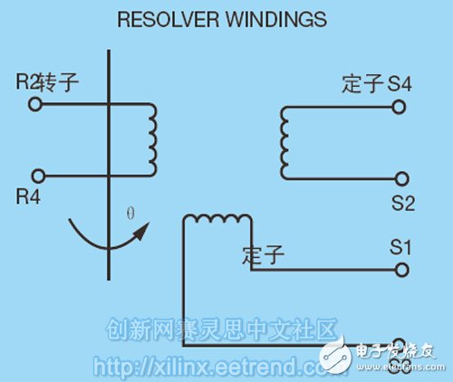
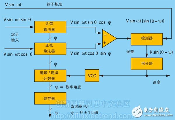
Angle sensors work well with FPGAs to help engineers create unparalleled machinery. Since humans invented the runner, we wanted to know how to improve the rotation efficiency of the runner by changing the accuracy. In the past few centuries, scientists and engineers have developed many methods to achieve this goal. The basic principles of wheel-axis systems have been widely used, from cars, volume knobs, gears in various mechanical forms to simple trolleys. This principle is used in every mechanical system [1]. After many times of exploration, people found that the most important factor for the efficient operation of the runner is not the runner itself (why not completely renovate it?), but the shaft angle of the runner. The most effective way to measure and optimize the shaft angle is to use an angle sensor. Many angle sensors are available to optimize wheel cycle efficiency through axle monitoring and improvement; however, with an FPGA, you can achieve very significant results while improving axle/cycle efficiency in a wide range of applications. Before we get a detailed introduction to how engineers can best use Xilinx FPGAs to achieve this, let's briefly review some of the basic principles of angle sensors. Widely used today are two types of angle sensors, encoders and resolvers. The encoder is divided into two basic categories: incremental and absolute. The incremental encoder monitors two positions on the axle and can generate an A or B pulse each time the axle passes through these two positions. A separate external electric counter then interprets the speed and direction of rotation from these pulses. Although it is suitable for many applications, incremental counters do have some drawbacks. For example, in the case of a wheel axle stall, the incremental encoder must first be self-calibrated by switching back to a specified calibration point before starting the run. In addition, incremental counters are susceptible to electrical interference, resulting in inaccurate pulses being sent to the system, which in turn causes rotational count errors. Not only that, but many incremental encoders are optoelectronic devices – they can't be used to radiate hazardous areas if they have an impact on the target application. The absolute encoder is a sensor system that monitors the rotation and direction of the axle rotation. In absolute encoder based systems, the user typically connects the wheel to an axle having an electrical contact or a photoelectric reference. When the axle is running, the absolute encoder based system records the rotation and direction of travel while producing a parallel digital output that is easy to convert into code (most commonly binary or Gray code). The advantage of an absolute encoder is that it only needs to be calibrated once (usually in the factory) without having to calibrate before each use. In addition, absolute encoders are generally more reliable than other encoders. However, absolute encoders are generally expensive and they are not conducive to parallel data transmission, especially if the electronic system that measures their readings is far from the encoder. The resolver is, by itself, a resolver - an analog device whose output voltage is uniquely associated with the input shaft angle it monitors. It is an absolute position sensor with a 0o~360o rotation angle that is directly connected to the axle and reports speed and position. The resolver has many advantages over the encoder. The resolver is robust and capable of withstanding harsh environments with dust, oil, extreme temperatures, vibration and radiation. As a transformer, the resolver provides signal isolation and natural common mode rejection of electrical interference. In addition to these features, the resolver requires only four wires for angular data transmission, making it suitable for a wide range of applications from heavy industry to micro-systems to the aerospace industry. The brushless resolver has been further improved without the need to connect to the slip ring of the rotor. Therefore, this resolver is more reliable and has a longer service life. The resolver uses two methods to obtain the output voltage associated with the shaft angle. In the first mode, the rotor windings as shown in Figure 1 are excited by an alternating signal and the outputs are from two stator windings. Since the stator is mechanically positioned to the correct angle, the output signal amplitude is related by the triangular sine and cosine of the shaft angle. Both the sine and cosine signals have the same phase as the original excitation signal; only their amplitude is modulated by the sine and cosine as the wheel rotates. Figure 1 – Decomposer rotor excitation In the second mode, the stator windings are excited by alternating signals that are orthogonal in phase. A voltage is then induced in the rotor windings. The amplitude and frequency of the winding are fixed, but the phase shift varies with the angle of the shaft. The resolver can be placed in the position where the angle needs to be measured [2]. Electronic devices, in general, refer to resolver-to-digital converters (RDCs) that can be placed where the digital output needs to be measured. The analog output of the resolver (with wheel angular position information) is then converted to digital form by RDC. In general, the two outputs of the resolver are applied to the sine and cosine multipliers of the RDC [3]. These multipliers combine a sine and cosine lookup table and a function to form a multiplying digital-to-analog converter. Figure 2 shows its function. Figure 2 – Blocker of the Decomposer Digitizer (RDC)
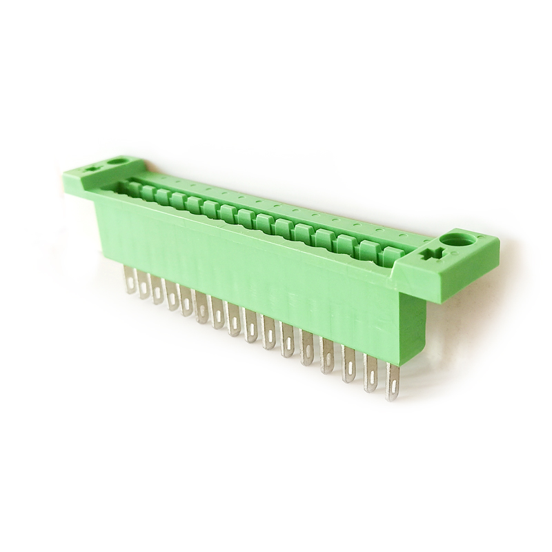
The composite terminal is a typical representative of the connector (CONNECTOR), which is composed of a plug (female) and a socket (male) to realize the connection function. For the transfer of voltage, current and signal, this series is characterized by safe, reliable and stable contact, and is mainly used in electric power, communication, industrial control and other industries.
composite terminal block,component terminal block,composite terminal block adapter Sichuan Xinlian electronic science and technology Company , https://www.sztmlch.com

