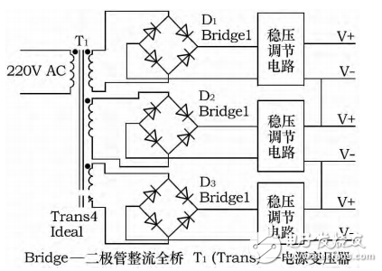
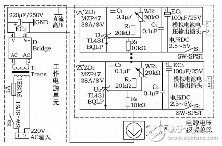
In the electric vehicle BMS (battery management system) inspection, a 105-series series lithium-ion battery simulator is required to test the BMS measurement accuracy of each cell voltage, using a 6-digit half-voltmeter reading and BMS measurement. Values ​​were compared to assess the accuracy of BMS battery voltage measurements. Requires simulator: 1 each voltage of the simulation is independently adjustable, the adjustment range is 2.5~4.5V; 2 voltage stability is within 2mV; 3 output current can meet the requirements of BMS measurement front end, no need to consider the charging of analog battery Features and equalization. Since the battery is a series structure, it is common practice to use 105 independent DC power supplies, and they are serially connected in series. There are two methods: 1. The mains receives 12V DC through the isolated AC-DC, and then gives more An isolated DC-DC (12V to 5V) power supply, 5V voltage and then through the adjustable voltage regulator, to obtain the analog battery voltage output, they are connected in series at the end, as shown in Figure 1; 2 using multiple transformers, each transformer has Multiple secondary windings, each of which simulates a battery. After the secondary side winding output voltage is rectified, filtered, and regulated, its positive and negative outputs are connected in series, as shown in Figure 2 (only one transformer is drawn in the figure), and each analog value is obtained. Figure 1 multiple DC-DC series The working mode of Figure 1 requires 105 isolated switches DCDC, which is large in size and high in cost. At the same time, the noise of DC-DC is above tens of millivolts, which cannot meet the measurement requirements. In the working mode of Figure 2, dozens of transformers need to be customized, and the ordering period is long and the volume is large. In order to solve the above problems, the author designed and built a set of simulators. Figure 2 DC output of multiple transformers in series The simulator consists of a working power supply unit, a constant current source unit and a battery voltage simulation unit. The working principle is shown in FIG. In the figure, SW-SPST represents a single-pole single-throw switch to simulate a wire breakage fault; T1 (Trans) represents a power transformer; WR1 and WR2 are variable resistors; Bridge represents a diode-rectified full bridge; and FUSE represents a fuse. The output voltage of the transformer T1 is rectified and filtered to generate DC high voltage. Each TL431 circuit is connected in series. Adjusting the multi-turn potentiometer of each channel can change the corresponding voltage output (output range: 2.5~4.5V), and at the same time can stabilize it. Within 0.2mV. Here TL431 is equivalent to an adjustable reference source, the Zener is used to protect the TL431. The 25mA constant current source is connected in series with the analog battery to provide operating current. Since the TL431 has a maximum holding current of nearly 100 mA, the constant current source in Figure 3 can be selected to be 25 mA. Figure 3 simulator schematic In response to the specific needs of electric vehicle BMS testing, the author of this paper used a solution based on the application of TL431 in the design of the battery voltage simulation part. The constant current source is used in the simulator to provide a constant operating current to the TL431 to avoid the effects of power supply fluctuations on output accuracy. The constant current source in this design has two main functions. 1) "Absorb" fluctuations in the 220V AC voltage. Since the power supply voltage fluctuates from +10% to -15%, the TL431 also changes, so it must withstand fluctuations of several hundred volts on the constant current source while still maintaining a constant loop current. If the constant current source is not used and the current limiting resistor is added, the current on the current limiting resistor fluctuates over a wide range, and the resistance of the resistor cannot be selected. In fact, the fixed resistor cannot meet the requirements.
ZGAR LEA BOX Vape
ZGAR electronic cigarette uses high-tech R&D, food grade disposable pod device and high-quality raw material. All package designs are Original IP. Our designer team is from Hong Kong. We have very high requirements for product quality, flavors taste and packaging design. The E-liquid is imported, materials are food grade, and assembly plant is medical-grade dust-free workshops.
Our products include disposable e-cigarettes, rechargeable e-cigarettes, rechargreable disposable vape pen, and various of flavors of cigarette cartridges. From 600puffs to 5000puffs, ZGAR bar Disposable offer high-tech R&D, E-cigarette improves battery capacity, We offer various of flavors and support customization. And printing designs can be customized. We have our own professional team and competitive quotations for any OEM or ODM works.
We supply OEM rechargeable disposable vape pen,OEM disposable electronic cigarette,ODM disposable vape pen,ODM disposable electronic cigarette,OEM/ODM vape pen e-cigarette,OEM/ODM atomizer device.
Disposable E-cigarette, ODM disposable electronic cigarette, vape pen atomizer , Device E-cig, OEM disposable electronic cigarette ZGAR INTERNATIONAL TRADING CO., LTD. , https://www.szvape-pods.com


