One- and three-pole method for measuring soil slope resistivity Where the soil resistivity needs to be measured, the buried earthing geometry is a known grounding body. The grounding resistance of the grounding body is measured according to the method described in the first section of this chapter, and then the soil resistivity is calculated. For vertical grounding bodies, the grounding resistance is Ï=2Ï€LR/1n4L/d Where Ï - soil resistivity, Ω · m; L——the depth of the steel pipe or round steel buried in the soil, m; D——the outer diameter of the steel pipe or round steel, m; R——Measured grounding resistance of the grounding body, Ω. Soil resistivity when using flat iron as a horizontal grounding body Ï=2Ï€LR/1n4L2/bh Where L is the length of the flat iron, m; B——the width of the flat iron, m; H——the depth of the flat iron centerline from the ground (approx. burial depth), m; R——Measured grounding resistance of the grounding body, Ω. When measuring, a steel pipe with a length of 3m and a diameter of 50mm (or a round steel with a length of 3m and a diameter of 25mm) or a flat iron with a length of 10~15m and 40*4mm can be buried in the soil as a grounding body. It is 0.7 - 1m. When measured by the three-pole method, the soil near the grounding body plays a decisive role. The soil resistivity measured by this method mainly reflects the soil condition near the grounding body. If necessary, several points should be selected in the grounding grid area. Second, quadrupole method, soil resistivity The wiring for measuring soil resistivity by the quadrupole method is shown in Figure 14-6. It can be measured by current-voltage method or by using a grounding resistance meter with four terminals (see Figure 14-7). Four uniform round steels having a diameter of 1.5 cm and a length of 0.5 m were used as electrodes, and the buried depth b was 0.1-0.15 m, and the electrode distance a was 2-3 m. During the measurement, the current I is applied from the outer electrodes C1 and C2, and the potentials appear on the electrodes P1 and P2, respectively. Up1=ÏI/2Ï€[1/a-1/(2a)] UP2=ÏI/2Ï€[1/(2a)-1/a] The potential difference between the two poles is Up1-Up2=ÏI/2Ï€a Where I - ammeter reading, A; A——the distance between electrodes, m; Ρ——soil resistivity, Ω·m, So Ï=2Ï€aU/I (current, voltmeter method) Or Ï=2Ï€aR (grounding resistance meter method) Where R is the measured value of the grounding resistance meter. The range of soil resistivity measured by the quadrupole method is related to the distance α between the electrodes. When α is small, the obtained soil resistivity is only the resistivity of the earth's surface layer. When measuring, select 3~4 points for measurement, and take the average value as the measured value. Considering that the soil resistivity is greatly affected by the season. Therefore, the measurement results should be corrected, ie Maxmax=Φ Ï Where Φ is the soil drying coefficient (see Table 14-1). If the measurement is dry season, take the smaller value in the table, and vice versa. It can be seen from Table 14-1 that the horizontal grounding body with a depth of 0.8 m has a variation of soil resistivity of nearly 50% in the dry season and the wet season. In summary, when measuring the soil resistivity by the three-pole method, the soil near the grounding body plays a decisive role, and only reflects the situation near the grounding body to a large extent. If necessary, several measurements should be selected in the proposed grounding grid area. When the soil resistivity is measured by the quadrupole method, the range reflected by the electrode is related to the distance a between the electrodes, and the reflected depth increases with the increase of a. When the a is small, the soil resistivity is only the resistivity of the earth's surface layer. When measuring, select 3-4 points for measurement, and take the average of multiple measurements as the measured value. For large-area grounding grids, it is recommended to use the four-pole method in the electrical measurement method for measurement. For the specific measurement methods, the reader can refer to the relevant part of the "Guidelines for the Measurement of Power Frequency Characteristics of Grounding Devices".
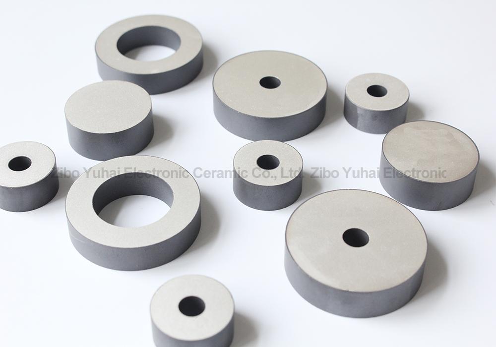
Barium titanate lead-free piezoelectric
ceramics are important basic materials for the development of modern science
and technology, which was widely used in the manufacture of ultrasonic
transducers, underwater acoustic transducers, electroacoustic transducers,
ceramic filters, ceramic transformers, ceramic frequency discriminators, high
voltage generators, infrared detectors, surface acoustic wave devices,
electro-optic devices, ignition and detonation devices, and piezoelectric
gyroscope and so on.
Application: military, ocean, fishery, scientific research,
mine detection, daily life and other fields.
Piezoelectric Ring,Lead Free Piezoelectric Ring,Piezo Electric Ring,Lead Free Piezo Rings Zibo Yuhai Electronic Ceramic Co., Ltd. , https://www.yhpiezo.com


Soil resistivity is an important data for the design of grounding grids. There are two methods: three-pole method and four-pole method.