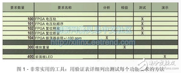
One of the most exciting moments in an engineering design project was when the hardware was first moved to the lab to begin integration testing. This phase of the development process usually takes a long time and puts a lot of pressure on all project engineers. However, existing tools and methods can reduce stress and help advance the project. Let's take a look at how to minimize any problems that can occur while advancing the design to a higher level, and how to get through the debugging phase quickly and smoothly. I have to imagine how to test from the first day. All engineers know that as the development process progresses, the cost of modifying the problem will increase accordingly. Once the design is finalized and put into production, the cost of modifying the pinout error is necessarily higher than the cost of the earlier design evaluation. In addition, there are also cost issues in testing and integration. The sooner you consider hardware, FPGA, system, etc. test problems and write test specifications, the easier it is for the engineering team to consider the necessary test points, connections, and functionality. The purpose of the test is to ensure that a safety system that meets the specific requirements of the user can be introduced. Therefore, we must ensure that the test reflects all requirements, while functional testing requires that process delivery be achieved and design requirements be tracked (ie, each test should meet its needs). In addition, it is a good practice to edit the design verification model to detail the method of testing each functional requirement, such as a specific test, analysis or read method (provided that it is clear or tested earlier on another project). Related requirements). The documentation (Figure 1) may also cover which tests are required for design verification and which are used for production runs. Completing the above documentation early in the project phase ensures that the system design team and the test equipment design team get a clear, basic approach. However, the design engineer must also ensure that the underlying hardware is correct before performing functional testing. They usually require hardware-level test specifications that include power, performance, and basic hardware verification, while hardware basic verification needs to be done before functional testing. It is important to know which test equipment is needed and what kind of performance, such as the need to analyze the signal generator and logic analyzer to provide sufficient memory depth and operating frequency? In addition, you need to know if you need more specialized test equipment, such as arbitrary waveform generators, high stability frequency references, and so on. What should be included in the design phase should include several design features and functions during the hardware design process to make board testing more convenient. The relevant requirements may be simpler or deeper. The simplest and most common test rule is to place test points on all voltage sources, which avoids the possibility of damage when interrogating solder joints. However, there is a better way to simplify the test by having the pad returning to ground (0V) close to the voltage test point. If a high value resistor is used to protect this test point, the current in the event of an unexpected short circuit in the test can be limited. We can also consider adding test pins to these pads to connect them to an automated test system that can then record results during production runs. In addition, the ability to monitor the clock and reset the output is critical. Therefore, it is not a good idea to place test points on the reset line. In addition, you should ensure that the unused clock buffers are properly terminated and test points are added to facilitate interrogation of the clock. In addition, you can consider adding test ports to signal injection and extraction through signal generators, logic analyzers, or other test tools. Boundary scan testing is useful for reducing hardware design risks early in the testing phase. To help the prototyping meet power requirements, it is usually better to connect low-value resistors (10 milliohms, 100 milliohms, etc.) to the output of the voltage regulator, if possible, to accurately measure the current on the power rail. For the same type of design that the industry is the first to achieve (that is, the first time a new product is actually built), we should probably make more in-depth design decisions, such as separating the power supply from downstream electronics. In this way, we can ensure that the power supply and power-on sequence work properly, thus avoiding excessive stress or damage to downstream components. An example of a more detailed front-end design phase that helps test the test is to ensure that the JTAG port has more use than programming all FPGAs or processors in the system, such as by boundary scan testing. Initial hardware verification, etc. Boundary-scan testing is useful for reducing hardware design risk early in the testing phase, as well as optimizing the design to ensure maximum coverage of boundary-scan devices. A wide range of FPGA devices can also provide a way to monitor the temperature of the chip using a temperature diode. Need to find a way to provide a constant current to the diode. Measuring the chip temperature helps us ensure that the junction temperature does not exceed the rating. Defining Hardware Features When you first arrive at the lab, the first thing you need to do is determine if the hardware underlying modules are suitable for further testing. The related checks include the initial power-on test of the module, which is a stressful process. Just get the module, you want to ensure that it is put into production accurately, and can successfully achieve the first power-on start. The first step is to ensure that all components are in place, pin "1" is properly positioned, and any components with polarity are placed accurately. Designs often include many components that do not need to be checked for positioning, such as those that are suitable for different versions or different build options. Make sure that all components are properly seated to see if they meet the design requirements, especially if only one pull-up or pull-down resistor should be in place and the configuration mode is selected. After checking the components on the printed circuit board, the next step is to power up the board for the first time. This is a very tense moment for any engineer. However, the test specifications developed during the design phase (test points, current sense resistors, etc.) will play a significant role in this. The first step is to ensure that the power output of the load point and other regulators does not short return. You may find low impedance on the power rail of the on-load device (with high current requirements), but the impedance should be greater than 1 ohm. If you are sure that all power rails are not shorted, then the next step is to power up. When I first power up, I tend to adopt a two-stage approach. The first stage uses low voltage (0.5V) and low current to ensure that no short circuit between the signal layer or voltage rail is missed; the second stage is to use the correct operating voltage within the set current limit. Power up to see if you get the expected current (don't forget the inrush current problem). After successfully powering up the design, the next step is to determine if the power-up is sequencing, resetting, and whether the clock is working as intended. Remember to ensure that the reset time exceeds all clocks and is stable before release. The next step in clarifying the hardware features is to ensure that the hardware is visible through the JTAG chain, which allows us to not only program the FPGA but also perform boundary scan tests. Boundary-scan testing can help us quickly test the interconnections between devices, and test memory to ensure that it works properly, such as developing loopback connectors and rotating input and output. JTAG and Boundary Scan tests eliminate design risk before further detailed testing. Committed to simplifying RTL In addition, you should take full advantage of the resources provided by the FPGA, especially the Xilinx System Monitor and XADC, which is very useful for monitoring the voltage rails on the chip, which in turn helps to verify the power integrity analysis performed during the design phase. In addition, the above technology can also easily report the chip temperature, which is helpful for environmental testing and power consumption of the chip temperature. In most cases, simplifying the RTL design and using the resources provided by the FPGA can be extremely helpful in pinpointing areas that do not work as expected. What should I do if I have a problem? Under the above circumstances, do not rush to make changes immediately. First, re-examine the design, especially the design information such as schematics and data sheets. If the problem is related to the FPGA, you should check that the pin constraint file is suitable for your design needs, as it is possible that the file is out of sync with the design. If you can't find any obvious mistakes at the moment, you may want to take advantage of the Internet and go online to see if other engineers have encountered the same problems as you. There are many forums on the web where you can ask other designers. Both Programmable Planet and the Xilinx Forum offer extensive support for FPGA-based designs. At the end of the day, hardware debugging is a challenging but rewarding component of engineering. If the test problem is taken into account in the early stages of the design and the elements required for the test are included in the design, the debugging work can be significantly simplified. Using all available resources such as ChipScope, System Monitor and XADC to debug the system, plus the proper use of traditional test equipment, we can successfully complete the development work. Interactive Whiteboard For Teaching Interactive Whiteboard For Teaching,Smart White Board,Interactive Smart Whiteboard,Electronic Digital Portable Whiteboard APIO ELECTRONIC CO.,LTD , https://www.displayapio.com
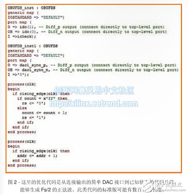
If your design is complex at both the hardware and FPGA levels, a simplified version of RTL will help test the interface between the board and the FPGA and peripherals (Figure 2). This is especially true for high-speed interface designs. We can combine the optimized RTL and Xilinx ChipScopeTM tools to capture data and the Block BRAM preloaded with data patterns to motivate. This method is especially useful for connecting FPGAs with ADCs and DACs. In this case, you should use the reprogrammable features of the FPGA to maximize design development and perform parameter testing of ADCs and DACs, such as noise/power ratio, spurious-free dynamic range, and effective bits (effecTIve-number) -of-bit) calculations, etc. 
As you progress through the test plan step by step, you may encounter one or two issues, such as failure to achieve the intended functionality, or failure to meet the required level of performance. Don't worry, we can use many survey methods to determine the source of the problem and the corrective actions required.