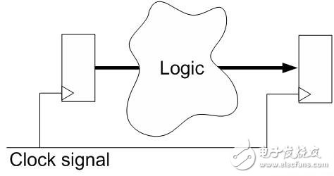
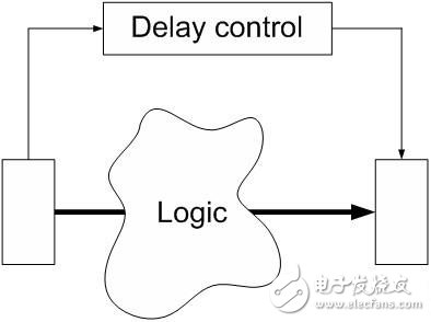
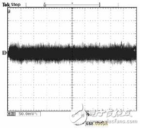
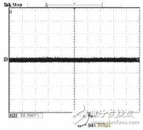
Currently, the primary measure of processor performance is the clock frequency. Most integrated circuit (IC) designs are based on a synchronous architecture, while synchronous architectures use a globally consistent clock. This architecture is very popular and many people think it is the only way to design digital circuits. However, there is a very different design technique that is about to come to the forefront: asynchronous design. The main driving force behind this new technology comes from the development of silicon technology. As the structure of silicon products shrinks to less than 90 nanometers, reducing power consumption has become a top priority. Asynchronous design has the advantages of low power consumption and more reliable circuit, which is seen as a way to meet this need. Asynchronous technology has been left out for a number of reasons, the most important of which is the lack of standardized tool flows. The IC design team is under tremendous pressure, including the rapid delivery of equipment, the use of high-level programming languages ​​and standard event-driven architecture (EDA) tools to help with tasks such as synthesis, timing, and verification. If an asynchronous design can use such a tool, it is expected that more devices with asynchronous logic components will appear. In the past, small asynchronous circuits were only used as a complement to synchronous circuits. Just recently, the newly released commercial devices are based primarily on asynchronous design. But such devices are targeted at niche markets, such as embedded sensors that require ultra-low power consumption and stable current. We are witnessing the emergence of a universal digital signal processor (DSP) core based entirely on asynchronous logic. Whether it's an IC designer or an end user, the benefits it brings are numerous. Synchronous and asynchronous The current digital design actually uses synchronous design techniques. For historical reasons, this approach has been improved and design tools have evolved. There is currently a standard stream based on high-level languages ​​for rapid development. Synchronous design also makes it easy to scale device performance. Designers only need to increase the clock frequency to make the design faster. The synchronization method involves the creation of functional modules, each of which is driven by a finite state machine (FSM) controlled by a clock signal. The trigger is used to store the current state. When a clock signal is received, the trigger will update the stored value. The logic phase is essential in the DSP design process. These phases implement the operation and pass the results to the next stage. The figure below shows a simple model of a single stage. Asynchronous logic is used to calculate the new state of the circuit between two flip-flops. For example, the logic cloud can perform addition or multiplication. Logic logic Clock signal For asynchronous DSP cores, the logic phase is adjusted to eliminate the clock. The figure below shows the basic structure of this DSP architecture. Instead of controlling the latch line by the clock, it actually passes a completion signal to the next logic stage. The completion signal can be generated at the appropriate time based on the operations performed by the logic cloud. This local delay control ensures the stability of the circuit. Since the logic of the control circuit time is local, it can change the voltage, processing speed and temperature accordingly. Delay control Logic logic There are many different ways to design asynchronous designs, provided that the circuit is not controlled by a single clock. In most cases, asynchronous logic is used to solve specific problems through specialized circuit design. However, asynchronous logic can also be used as the basis for a complete DSP core, not just a tool that is occasionally needed in a design. Benefits include reduced power consumption, increased reliability, and low electromagnetic interference (EMI). The benefits of asynchronous design The reason for adopting asynchronous design is very attractive. In proper use, this approach enables lower power consumption and better EMI performance; it really simplifies the design by eliminating global clock skew. Lower power consumption: The most important benefit of asynchronous DSPs is the lower power consumption compared to synchronous DSP cores. In fact, this asynchronous core is orders of magnitude higher than the best synchronous DSP. As silicon products shrink in size, power consumption issues become more important. Since the line length is linear and the area is square, the silicon power consumption per unit area will increase as the size decreases. At present, digital designers have successfully solved this problem by reducing the voltage; however, due to the limitation of the voltage threshold, current semiconductor technology can no longer effectively reduce the voltage. In order to effectively utilize the newly added functions, it is necessary to reduce the power consumption of each function. In CMOS technology, the gate consumes energy when switching states. In a synchronous circuit, the clock needs to be switched multiple times, resulting in power consumption. A clock buffer is required to allocate clocks in a device or device partition. The clock buffer must be large enough to ensure that the clock skew is minimized. In other words, all points in the circuit must accept clock transitions at the same time. Clock distribution, often referred to as the Clock Tree, typically consumes almost half of the total system energy. The clock buffer at the bottom of the tree has a considerable fanout and a large volume, so the power consumption is high. A variety of techniques are currently being developed to eliminate the power consumption of switching logic, such as clock gating. To date, none of these technologies have enabled lower power consumption for asynchronous designs. Clock gating is not a must for asynchronous circuits. In fact, asynchronous circuits only consume energy when performing efficient operations. In other words, the power consumption of the asynchronous circuit will increase accordingly depending on the performance provided without adding circuitry. This means that without more adjustments, the device has a low standby current and its power consumption will increase with the actual performance provided. Better switching performance: In addition to lower power consumption, devices with asynchronous logic will have very low EMI. Whether it's an IC designer or an end user, the benefits it brings are numerous. A global or local clock is one of the biggest factors affecting EMI. Since the global clock in the synchronous circuit needs to be switched at the same time, the EMI emitted by the synchronous device will have a fairly significant peak at a certain frequency. EMI noise from high-speed devices will enter the power plane of the PCB. This noise will then appear in the external I/O or wiring, causing unwanted and often excessive radiation in the cable. The first line of defense uses decoupling capacitors, while the more expensive shielded or common mode choke coils will be used as the last line of defense. EMI on the power plane also complicates the design of the power supply. For high-speed synchronous circuits, the power supply must be filtered or over-stocked to match the voltage spikes generated on the power plane. These noise and power issues add up to the designer's design difficulty, especially when using a large number of high-speed DSPs in a particular design. Asynchronous logic design can alleviate or solve these problems by eliminating the need for a global synchronous clock. Significantly reduces EMI, making PCB design simpler and increasing system reliability. The lack of asynchronous circuit power ripple is quite compelling, indicating that better switching performance can be achieved. The following figure shows a typical difference between synchronous and asynchronous DSP power supply noise. These figures are screenshots of the oscilloscope that measure the noise generated by the high-performance DSP on the power plane. Figure 1: Synchronous DSP voltage ripple Figure 2: Asynchronous DSP voltage ripple In the eyes of IC designers, better switching performance represents a more reliable circuit. When the circuit is switched at the same time, a very large instantaneous current will be generated. It is shown as IR drop on the grid of the device. This means that a certain area of ​​the grid has a lower voltage at this time. This is an expected normal condition and is usually verified by design to ensure that the grid can withstand the expected maximum voltage drop. Sometimes this is also a limiting factor that prevents designers from further designing in specific areas of the logic. Eliminate clock skew: There are many reasons for using asynchronous design. Wafers below 90 nm are a trend in production. This can be demonstrated by the efforts of silicon manufacturers to correct a range of problems. They have begun to develop advanced technologies such as Interferometric Metrology. Try to make the minimum feature size of the mask smaller than the current exposure wavelength. Since these variables increase the amount of deviation of the device, it is important to control them in the process. The clock skew is defined as the time difference between the clock signal reaching different points in the circuit. Since all logic on the same clock must run in an orderly fashion, the clock skew must be kept to a minimum to ensure proper operation of the circuit. The higher the clock frequency of the device, the smaller the allowable deviation. As the feature size decreases, the problem of clock skew will become more serious. Compared to the previous, specific chips will be divided into "slow" chips and "fast" chips; due to the large increase in density, the variables in a single chip will also be reflected. The nature of this situation is significant for large single-chip synchronous devices. Avoiding such problems with an asynchronous DSP core. The DSP core is based on a small self-timer circuit. Therefore all timing is local to the small area associated with the logic block. Higher stability: Semiconductors are primarily affected by three physical properties: production process speed, supply voltage level, and temperature. If any of these characteristics change, it will cause the transistor to run faster or slower. The synchronization circuit must perform a static timing analysis (staTIc TIming analysis) at the best and worst state values ​​of the above parameters to ensure that the device is working properly. In other words, the synchronization circuit has a "cut point" that stops the circuit. Since asynchronous circuits are self-timed circuits, they only need to accelerate or decelerate as physical characteristics change. Because the logic that controls the self-timer is in the same area as the processing logic, environmental changes such as temperature and voltage can affect both. Therefore, asynchronous circuits have better resistance to transient changes such as dynamic voltage drops, and will automatically adjust to long-term temperature and voltage changes. Turned out: Universal Asynchronous DSP As various devices that successfully adopt asynchronous design techniques continue to emerge, asynchronous designs are receiving more and more attention. The advantages of asynchronous logic are well known. Includes low power consumption and a more stable design. Until recently, asynchronous circuits were only used when it was necessary. Due to academic bias, they are often seen as marginal products. Many commercial devices have now developed the above features for a variety of niche markets. The emergence of a general-purpose DSP core based entirely on asynchronous logic suggests that existing tools, technologies, and knowledge-created commercial products can be applied to a larger customer base. What's even more fascinating is that the device can be programmed and operated the same way as any existing DSP. In other words, this solution realizes all the advantages of asynchronous technology without affecting the availability. MW01 Smart Watch Mw01 Smart Watch,Mw01 Smartwatch,Smart Watch Mw01,Smartwatch Mw01 everyone enjoys luck , http://www.eeluckwatch.com


