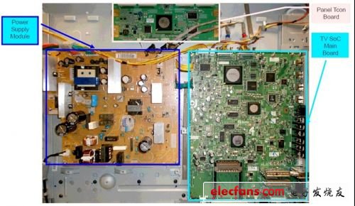
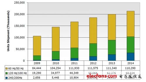
Evolution of television technology John Logie Baird first demonstrated the transmission of motion images in 1925. This groundbreaking development is recognized as the first true demonstration of television. Over the next few decades, the system has undoubtedly had many more subtle improvements, including advances in broadcasting, but the basis of television remains the same: receiving an analog signal and displaying it on a glass screen. Color replaced the black and white, rear projection products to complement the shortage of cold cathode tubes (CRT), cables and satellites become the medium of transmission, but ultimately the TV is still an analog display. Everything changed after the emergence of the world’s first high-resolution flat-panel TV in the mid-1990s. New TVs using plasma technology are only a fraction of the thickness of a CRT. New interface technologies such as Digital Visual Interface (DVI) and High-Definition Multimedia Interface (HDMI) soon followed, predicting the shift from analog TV to digital TV. However, this is only the beginning. HDMI allows high-resolution images with ever-increasing playback format sizes to be displayed on our home entertainment systems. The demand for bandwidth has begun to increase, and the limitations of existing television construction have become more apparent. Flat TV construction If we simply look at the main parts of a flat-screen TV, we will find: - Display panel (plasma, liquid crystal display, organic light emitting diode) - Timing controller (Tcon) board for driving panels - An image processor board with a system-on-a-chip (SoC) IC. It is responsible for converting the incoming stream of information from the source into the correct format for the Tcon. - Power supply module Figure 1: General flat TV disassembly diagram When the size of a flat-panel TV is still small, the SoC and Tcon can be fixed on the same printed circuit board (PCB). However, as the screen size increases, it continues to be too expensive (and too heavy) to continue with a large PCB, thus gradually forming a solution for the two boards. When SoCs and Tcons were placed on different PCBs, an interconnected technology was needed to transmit the signals between them. In the mid-1990s, TV manufacturers adopted LVDS interface technology as the de facto standard. LVDS technology LVDS (Low Voltage Differential Signaling) was developed by National Semiconductor in the early 1990s and was first used in televisions in 1996. After 16 years, it remains the dominant technology for this application. The real name for this technology is actually flat panel display (FPD-Link), but because it is the first large application of LVDS, many engineers use FPF-Link and LVDS as synonyms. LVDS is defined in the ANSI/TIA/EIA-644-A standard, which was developed by the Data Transmission Interface Board TR30.2 in 1995. The standard of development for the year. It is a low voltage, low power differential technology that is primarily used in wire drive applications for point-to-point and multi-drop connections. This standard recommends a maximum data rate of 655 Mbps, but the recent introduction of high-speed LVDS has increased to approximately 1.2 Gbps. The LVDS is designed to drive 7 data bits per clock. A separate clock channel is required for every five data channels, which means an increase of approximately 16% of the cable fixing cost. LVDS and its expandability LVDS has been popular in the industry for many years, and recent advances in resolution and playback formats have led to a significant increase in bandwidth. TVs with 60Hz and 120Hz update frequencies are already available in stores, and the 2012 CES show even displays 4Kx2K TVs. As a result, the number of LVDS lines used to support these bandwidths has increased considerably, causing TV manufacturers to add more cost and complexity to production. As the market estimates that the number of TV shipments with higher update frequency will grow steadily, the LVDS restrictions will become more apparent. Cost pressures and engineering constraints will force TV manufacturers to seek alternative solutions. Figure 2: Estimation of 60/120/240Hz TV shipments
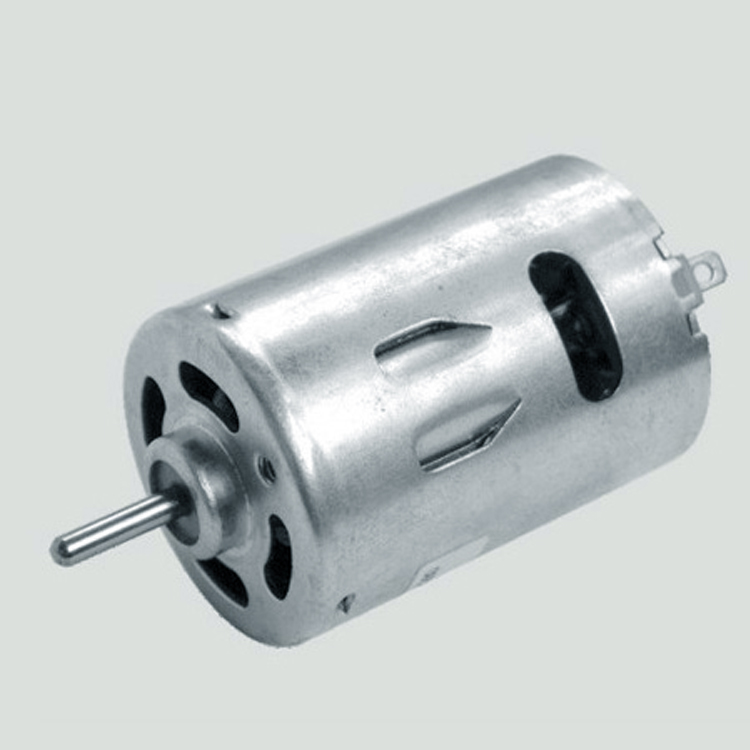
Electric dc motors were the
first type widely used, since they could be powered from existing
direct-current lighting power distribution systems. A electric Dc Motor's speed can be controlled over a wide range, using either a variable supply
voltage or by changing the strength of current in its field windings. Small electric dc motor are used in tools, toys, and appliances. The universal motor
can operate on direct current but is a lightweight motor used for portable
power tools and appliances. Larger electric dc motor are used
in propulsion of electric vehicles, elevator and hoists, or in drives for steel
rolling mills.
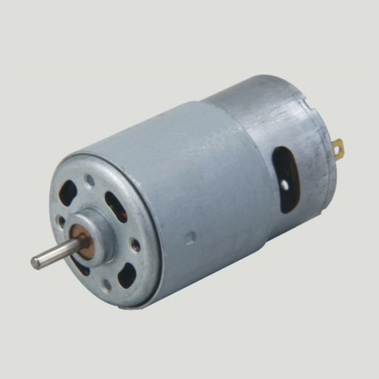
Areas of application: the Electric Dc Motor rotor part of the armature iron core, armature, commutator, such as equipment, electric dc motor is suitable for most electronic products, such as electric screwdriver, laser, smart home, gas valve, etc
Applications:
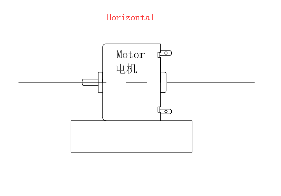
Method of use: the best stable in
horizontal plane, installed on theelectric dc motor output
shaft parts, cannot use a hammer to knock, knock prone to press into the electric
dc motor drive, may cause damage to internal components, and cannot be
used in the case of blocked.
Operating
temperature range:
Electric dc motor should be used at a temperature of -10~60℃.
The figures stated
in the catalog specifications are based on use at ordinary room
temperature catalog specifications re based on use at ordinary room
temperature (approximately20~25℃.
If a electric dc motor is used outside the prescribed temperature range,the grease on the gearhead
area will become unable to function normally and the motor will become unable
to start.Depending on the temperature conditions ,it may be possible to deal
with them by changing the grease of the motor's parts.Please feel free to
consult with us about this.
Storage
temperature range:
Electric dc motor should be stored ta a temperature of -15~65℃.
In case of storage
outside this range,the grease on the gearhead area will become unable to
function normally and the motor will become unable to start.
Service life:
The longevity of
geared motors is greatly affected by the load conditions , the mode of
operation,the environment of use ,etc.Therefore,it is necessary to check the
conditions under which the product will actually be used .The following
conditions will have a negative effect on longevity.Please consult with us
should any of them apply.
â—Use with a load
that exceeds the rated torque
â—Frequent starting
â—Momentary reversals
of turning direction
â—Impact loads
â—Long-term
continuous operation
â—Forced turning
using the output shaft
â—Use in which the
permitted overhang load or the permitted thrust load is exceeded
â—A pulse drive
,e.g.,a short break,counter electromotive force,PWM control
â—Use of a voltage
that is nonstandard as regards the rated voltage
â—Use outside the
prescribed temperature or relative-humidity range,or in a special environment.
â—Please consult with
us about these or any other conditions of use that may apply,so that we can be
sure that you select the most appropriate model.
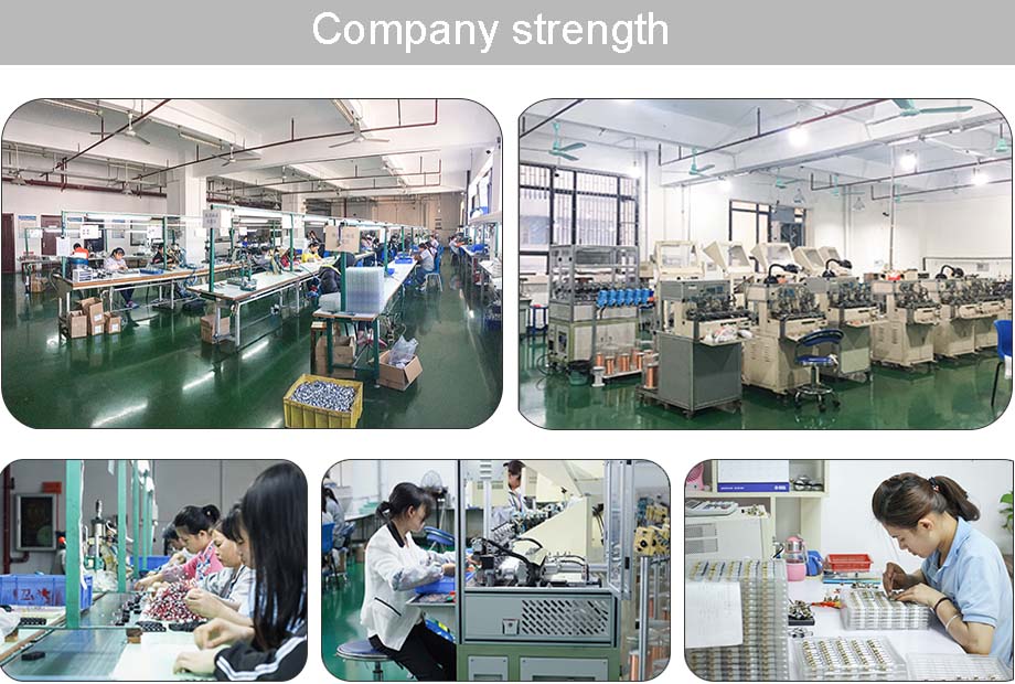
when it come to
volume production,we're a major player as well .each month,we rurn out
600000 units,all of which are compliant with the rohs directive.Have any
questions or special needed, please contact us, we have the engineer group and
best sales department to service to you Looking forward to your inquiry. Welcome
to our factory.
Electric Dc Motor Electric Dc Motor,Mini Electric Motor,12V Electric Motor,Electric Motor Gearbox Shenzhen Shunchang Motor Co., LTD. , https://www.scgearmotor.com