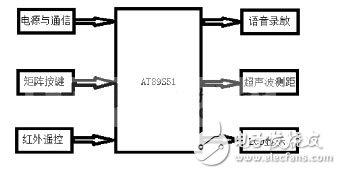
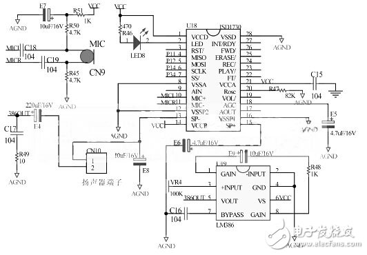
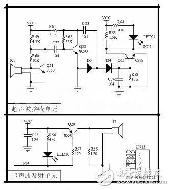
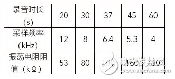
Overall design The voice ranging system requires the following functions: When the moving target vehicle is put into storage, the ultrasonic module (integrated temperature compensation) measures the distance between the target vehicle and the limit position of the storage area in real time, and the operator presses the remote controller to activate the voice broadcast module. Start broadcasting measurement data. The temperature measurement is realized by the 1-Wire device DS18B20. The core device of the voice broadcast is the ISD1730 produced by Winbond, and the single-chip microcomputer selects the 51 series AT89S51. In addition, there are LCD display, matrix keyboard, infrared remote control and other units. The voice chip ISD1700 is the key component of the whole system. This paper focuses on the performance characteristics, circuit design and programming points of the ISD1730. Figure 1 is a block diagram of the system structure. Figure 1 overall structure block diagram ISD1730 is a high-integration, high-performance, high-quality voice recording and playback chip, which contains automatic gain control, microphone preamplifier, speaker driver and other circuits; can handle up to 255 segments of voice information, can be multi-segmented and on-chip Specialized storage system to manage; sampling rate can be adjusted between 4KHz and 12KHz, support independent button and SPI two operating modes; with strong load capacity, can directly drive small speakers; with 4 preset sound effects, recording data stored in FLASH Inside, without any compression, it has better sound quality. In order to facilitate the control of the single-chip microcomputer, this paper puts the ISD1730 in the SPI working mode. According to the chip manual, the ISD1730 can directly drive the 8Ω impedance speaker or the ordinary earphone, but in order to enhance the load capacity and ensure the voice transmission distance, the power is designed in the rear part of the ISD1730. Amplifier Circuit - LM386, as shown in Figure 2, the power amplifier circuit can provide more than 50 times the gain, can drive the speaker with 16Ω impedance. Figure 2 ISD1730 voice recording and playback system Ultrasonic ranging unit Combined with the actual situation of the reservoir area, this paper uses discrete components to design the ultrasonic ranging circuit itself, as shown in Figure 3. The ultrasonic probe has a center frequency of 40 kHz, a direction angle of 60 degrees, and an operating temperature of -20-70 ° C, which can meet the needs of the reservoir area. Figure 4 is a physical design of the ultrasonic ranging module. Figure 3 Schematic diagram of ultrasonic ranging unit Other unit The rest of the unit functions as follows. The LCD unit is used to display experimental data for system debugging. The matrix keyboard unit is used to implement key input; the infrared remote control unit is responsible for triggering of the whole system, and the integrated infrared receiving head is connected with the single chip Int0. When the user presses the remote control button, Int0 generates an interrupt, and the single chip sends a voice broadcast instruction. software programming ISD1730 software design SPI related commands In SPI mode, the ISD1730 related commands are shown in Table 1. Note that the chip pin 2 is connected to a blue LED to indicate the working state of the voice chip. To enable this LED, all command bits bit4 must be set to 1. Table 1 ISD1730 related commands ISD1730 programming points The ISD1730 uses flash as the memory, and the memory address is 0x00~0xff, where 0x00~0x0f is the sound storage unit. To achieve voice broadcast, you need to pre-record distance data. The following arrays can be used as data cache: Unsigned char code voic_mem[]={ //Define the voice storage unit 0x10, 0x13, 0x14, 0x17, // voice “0â€, “1†start address and end address 0x18, 0x1b, 0x1c, 0x1f, // voice "2", "3" start address and end address 0x20, 0x23, 0x24, 0x27, // voice "4", "5" start address and end address 0x28, 0x2b, 0x2c, 0x2f, // voice "6", "7" start address and end address 0x30, 0x33, 0x34, 0x37, // voice "8", "9" start address and end address 0x40, 0x43, 0x44, 0x47, // voice "hundred", "ten" start and end addresses 0x48, 0x4b, 0x4c, 0x4f, // voice "point", "meter" start and end address }; The voice recording of ISD1730 has 5 sampling frequencies. The higher the sampling frequency, the better the voice quality, but the shorter the recordable time, the sampling frequency depends on the external resistance of the chip's ROSC pin, recording duration, sampling frequency and oscillation resistance. The corresponding relationship is shown in Table 2. Table 2 Correspondence between recording duration, sampling frequency and resistance of oscillating resistor The connection setting frequency of Figure 2 is 8kHz. According to the ISD1730 technical manual, when the sampling frequency is 8kHz, each memory unit can record 125ms voice. In the experiment, 16 segments of voice need to be recorded. The program plans to occupy 4 memory for each voice segment. The unit, that is, each voice segment takes 0.5s. Ultrasonic ranging programming points The distance measurement and conversion is done in the INT1 interrupt service sub-function. The sub-function starts the counter to calculate the duration of the received echo, and then calculates the measured distance according to the ultrasonic propagation speed. At this point, pay attention to increase the delay function to ensure the measurement is completed. The ultrasonic propagation speed is susceptible to temperature, so it is necessary to increase the temperature measurement to correct the ultrasonic propagation speed, thereby realizing the compensation of the measurement distance. When reading the temperature, pay attention to the data conversion. Convert the lower 8 bits and the upper 8 bits into a 16-bit number. The upper 5 bits are the same, the representative symbol, the lower 11 bits, and the temperature is the binary number, which is high. 7 bits are temperature integers, and the lower 4 bits are temperature fractions; if it is a negative temperature, the complement is read from the temperature register, and the complement code should be reversed to get the original code. The decimal places of the DS18B20 can be understood as follows: After the MCU issues the Read Temperature Register command, the DS18B20 will return 9 sets of data. The lower 4 bits of the first set of data represent the temperature fraction, in other words, the 1 degree is decomposed into 16 4 The bit number is represented by a binary number, and the precision of the temperature fraction is 1/16=0.0625. Application and testing The system is installed on the sports target vehicle. When the target vehicle is put into storage, the remote controller is pressed, and the speaker continuously reports the distance between the target vehicle and the limit position. When the distance reaches the requirement, the target vehicle is stopped. After the actual test, the operator can complete the distance measurement outside the reservoir area with the system, and the measurement distance can be up to 4 meters, and the effect is satisfactory. Led Beads,Light Source Circuit Board,High Power Led Bead,Smd Led Beads Shenzheng Weifu Circuit Technology Co.Ld , https://www.wfcircuit.com


