Overview: 2 system structure In order to achieve the above purpose, the iron core and the coil are designed to obtain electric energy from the high-voltage line, and the obtained electric energy is converted into a steady current source through the switching power supply, and the nickel-hydrogen battery is charged by the charging enable circuit, and the charging control circuit is used for the battery. Voltage monitoring to control the charging mode, whether it is charging, whether it is stopped, and the information is transmitted to the main control system of the patrol robot. 3 Working principle According to the electromagnetic field theory, there is an alternating magnetic field in the high-voltage transmission line around the working state. According to the law of electromagnetic induction, the circuit in the magnetic field will generate an induced current. Under the premise that the transmission line is infinitely long, the magnetic flux line of the magnetic field generated by the transmission line is a concentric circle around it. For example, the current in the transmission line is I1. According to the Ampere loop theorem, the magnetic field strength at any point from the distance of the transmission line can be pushed out: H=I/2 πr(A/m)(1) Longhua Manxueling Trading Company , https://www.mxlvape.com
1 Introduction Robot line inspection refers to the use of robots to carry and detect communication instruments along the whole line. The robots complete the detection of line operation faults and the inspection of hidden dangers of safety accidents, and transmit the detected information to the ground in real time. Perform analytical processing. When operating on a normal ground, a small battery timing change is generally used. However, high-voltage transmission lines are distributed in the wild, crossing mountains and lakes, and when patrolling robots operate, energy consumption is large, and there is no power source available for charging at the scene, and frequent replacement of batteries during the line inspection process causes inconvenience, and this factor will Greatly limit the wide application of line-of-sight robots.
To this end, this paper studies the power supply system that supplies power to the robot by means of induction power.
The magnetic induction is: B = μI / 2πr (T) (2)
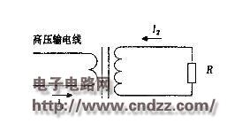
The aspect of B is tangent to the circle centered on the wire and perpendicular to the plane of the wire. If the robot is treated as a resistor R, a current I2 will be generated in the loop composed of the induction coil and the robot. The equivalent diagram is shown in Fig. 1. 
Figure 1 The equivalent of the circuit diagram of the power-carrying device The core of the research on the robot power system is how to efficiently convert the magnetic field energy around the transmission line into electrical energy. The key part is the design of the core and the coil.
(Please read the PDF for details)