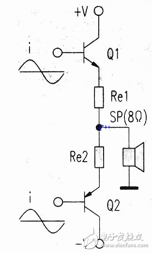
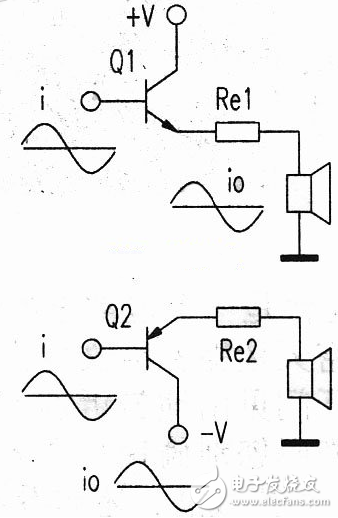
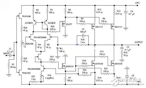
This article describes the Class A amplifiers for audio power amplifiers, including the characteristics of Class A amplifiers, power calculations, and circuit diagrams for single-ended Class A power amplifiers. Audio power amplifiers are classified into Class A amplifiers and Class B amplifiers. Class A amplifiers use two power tubes for positive half-period and negative half-cycle audio amplification, respectively. Therefore, the sound is loud, the sound quality is good, and the distortion is small. Also known as push-pull amplification. It is now widely used. Class B amplifiers use a single tube for half-cycle amplification. The disadvantages are low power, large distortion, poor sound quality, and low use. Class A power amplifiers do not have crossover distortion, and audio signals can be transmitted intact. Class A power amplifiers are the goal pursued by enthusiasts. What is the output power of a Class A amplifier? What is the power loss? These are the pre-theoretical calculations for the production of Class A power amplifiers. Class A power amplifiers mostly adopt the push-pull working mode in which NPN and PNP are paired. The push-pull type A power amplifier circuit can be regarded as consisting of two single-tube type A-type emitters. The NPN tube of the positive power supply and the PNP tube of the negative power supply operate in the Class A state, respectively, and amplify the entire audio signal. Output to the speaker. Push-pull type A power amplifier must know before commissioning and debugging, how much power do you do? How much quiescent current is needed? What is the supply current? What is the loss? This information is hard to find. Is the power indicated by some manufacturers on Class A amplifiers really so big? The buyer wants to verify. How to achieve the above goals? This requires a theoretical analysis of push-pull type A power amplifiers. Figure 1 is a class A push-pull amplifier output circuit, this output circuit can be broken down into Figure 2. Figure 1 Class A push-pull amplifier output circuit Figure 2 output circuit exploded view As can be seen from Figure 2, the current obtained by the horn is provided by the NPN and PNP triodes, respectively. The polarity of the audio signal input by the NPN power amplifier tube and the PNP power amplifier tube is the same. Class A working state is that the triode has current at any time while working. Regardless of the recent years of driving, many people sell the C-band receiving device of the China Star 6B at a low price. However, in general, these pots have been disintegrated due to severe corrosion for less than two years, so that no signal is positive or negative, and the last tube has current flowing. The single-tube class A working collector current waveform is shown in Figure 3. Taking a sine wave as an example, the quiescent current is the sine wave peak, that is, Io=lf, and the maximum current is 2 times the peak value, that is, Imax=21f=2I. This quiescent current setting ensures that the triode has current flowing through the entire signal period. To request the power output of the power amplifier, the effective value of the output current must be obtained. The rms current is shown in Figure 3. The sum of the areas of the shaded areas of the output current waveform: The output power of each tube A is P A 1 = I02Z (Z is the output impedance). NPN and PNP two final stage tube total output class A power is P A 2 = 2P A 1 = 2I02Z. The general speaker impedance is Z = 8 Ω. The formula is simplified to P A 2 = 2I02Z8 = 16I02z. Identification method: The circuit of the power amplifier part uses the same two power amplifier tubes, which is generally a class A power amplifier. Usb Megaphone,Megaphone With Usb,Megaphone With Bluetooth,Megaphone With Usb Port Shangqiu Huayitong electronic technology co., Ltd. , https://www.huayitongmegaphones.com

