Trench Cover,Trench Drain,Drain Cover,Steel Trench Covers Hunan Furui Mechanical and Electrical Equipment Manufacturing Co., Ltd. , https://www.thresher.nl
Maxim offers supervisory circuits with open-drain, push-pull, and bi-direcTIonal reset outputs. Customers often ask how these differ and how to determine which is most appropriate for a given applicaTIon. This application note offers explanations and guidelines.
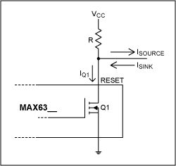
Open-Drain OutputThe RESET output of the supervisory circuit is the drain of an internal MOSFET, Q1 (Figure 1). An external pull-up resistor connected from RESET to a supply voltage is needed to create a logic signal output. VRESET goes low when Q1 turns on. RESET goes high impedance when Q1 turns off and VRESET goes to the supply rail. The pull-up resistor can be connected to a voltage supply other than the supply of the supervisory circuit. 
Figure 1. Open-drain output.
Take the source and sink capabilities of the supervisory RESET output into consideration when choosing the pull-up resistor; especially when RESET drives more than one device on the same bus. Choose a resistor low enough such that VRESET stays 'high' when Q1 turns off (VRESET = VCC-ISOURCE × R) and high enough such that VRESET stays 'low' when Q1 turns on. Keep in mind that Q1 now must conduct IQ1 = ((VCC-VLOW) / R) + ISINK. A nominal value of a pull-up resistor is 4.7kΩ.
The advantage of an open-drain output is the wired-OR capability; the disadvantage is a slow rise time and an additional external resistor. Connect the open-drain outputs of two or more supervisory circuits on the same bus to implement a negative logic ' OR 'circuit. The bus is low when the reset output of any one supervisory circuit goes low. The bus is high only when all the RESETs are high. This is most convenient when one wants to monitor multiple voltage supplies and trigger a reset when any one supply drops.
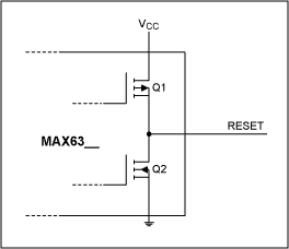
Push-Pull OutputA push-pull output consists of a pair of complementary MOSFETs (Figure 2). This configuration is similar to the output stage of a comparator. RESET output goes high when Q2 turns off and Q1 turns on, and goes low when Q2 turns on and Q1 turns off. 
Figure 2. Push-pull output.
The sink and source output current capabilities of the supervisor are specified in the electrical characteristics table. Make sure that the succeeding circuitry connected to RESET does not sink or source a high enough current to cause the output to deviate from the voltage level of the desired state .
Only one push-pull output can be installed on a bus. More than one circuit on a bus will cause conflict. The device with the 'stronger' source of sink capability dominates the resultant state.
The push-pull output offers high speed, almost rail-to-rail response both from low to high, high to low, and the capability to source or sink current.
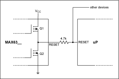
When interfacing a push-pull RESET output using a µP with bi-directional reset, connect a resistor (Figure 3) between RESET and the µP RESET. This allows the µP to issue commands to the system regardless of the state of the supervisor RESET. The bi-directional reset on a µP functions both as a driven RESET input and as an active system RESET driver. 
Figure 3. Interfacing to uPs with bi-directional reset.
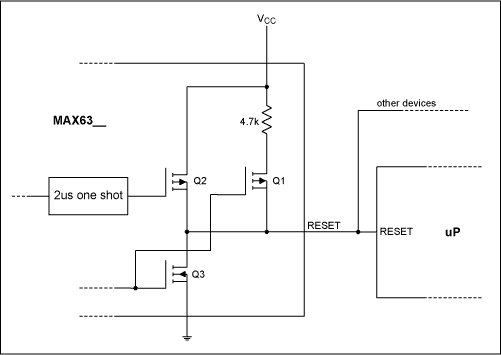
Bi-Directional Output (Maxim proprietary) When interfacing with a µP bi-directional RESET input / output which requires a fast reset rise time, Maxim provides supervisory circuits (the MAX6316 series) with a proprietary open-drain bi-directional reset output (Figure 4). It integrates an open-drain output (Q3) with an internal 4.7kΩ pull-up resistor. RESET goes low when Q3 turns on with Q1 and Q2 off. RESET goes high when Q3 turns off and Q1 turns on. To quickly bring RESET high, Q2 turns on for a short period of time (~ 2µs) after Q1 turns on and after VRESET has risen to a certain voltage (~ 0.65V). Q1 serves to reduce the power consumption of the supervisory circuit when Q3 turns on by disconnecting the internal pull-up resistor from the circuit. 
Figure 4. Bi-directional output.
One may suggest that just using an open-drain output and lowering the value of the pull-up resistor, thus increasing the source current, will achieve the same result as the added Q2. The fact is, there is a limitation on how low the pull-up resistor can be. The reset output of some µPs is rated only as high as 1.6mA sink current. When the µP reset goes low the voltage on the bus will be pulled to VRESET = VCC-1.6mA × R and this must be still low enough to be recognized as a logic low level. Reducing R (the pull-up resistor value) to improve the rise time may raise VRESET to above logic low when the µP RESET goes low.
ConclusionChoose an open-drain reset output supervisor when more than one supervisor is connected on the bus. Estimate the sink and source currents when using the open-drain reset output to pick the correct value of the external pull-up resistor. The open-drain reset output also comes in handy when the reset output high level has to be different from the supply voltage of the supervisor circuit.
Use a push-pull reset output supervisor when only one supervisor is needed on the bus, to eliminate the need of a pull-up resistor. When interfacing with a bi-directional reset output of a µP with only one supervisor, either use a push -pull reset output with an external resistor as shown in Figure 3, or use the Maxim proprietary open-drain bi-directional reset output. Note that the Maxim open-drain bi-directional reset output provides the fastest rise time.
When more than one supervisor is needed on the bus connecting to the bi-directional reset output of a µP the Maxim open-drain bi-directional reset output is the optimal choice.
Abstract: Maxim offers µP supervisors / voltage detectors with different reset output configuraTIons. The note describes the differences between open-drain, push-pull, and bi-direcTIonal outputs.