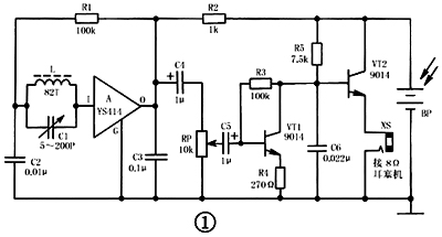
Solar radio circuit Solar energy is an inexhaustible energy source. Devices that directly convert solar energy (or other light energy) into electrical energy are called solar cells. With the increasing awareness of energy saving and environmental protection, solar cells are becoming more and more popular because of their rich energy, no pollution, long life, easy use and maintenance, and reliable performance. How to make a small medium wave AM radio powered by solar cells is fun and comfortable: you can use it to listen to news broadcasts and learn foreign languages ​​in the sun during the day and under the lights at night. Through the production, you can also master and understand the knowledge about solar cells, broaden your horizons, and lay the foundation for the further development and utilization of solar energy in the future. 1. The working principle of solar radio circuit The circuit of small solar radio is shown in Figure 1. It uses a miniature radio special integrated circuit A for high-frequency amplification and detection, followed by two transistors VT1, VT2 for low-frequency amplification and emitter output, and finally promotes 8Ω low-impedance earphones to play. Second, the solar radio circuit components selection BP adopts a finished solar panel with a size of about 35mm × 10mm, an open circuit voltage ≥ 2V, and a short circuit current ≥ 8mA. This kind of solar cell panel is made of single crystal silicon wafer technology, and its photoelectric conversion efficiency is stable. It has been widely used in calculators and other weak current appliances. The power output capability of a solar panel is closely related to its area. The larger the area, the greater the output power under the same lighting conditions. The advantages and disadvantages of solar panels are mainly measured by the two indicators of open circuit voltage and short circuit current. The amateur test method is: place the solar panel under direct sunlight and measure the output voltage at both ends with a multimeter, which can be regarded as an open circuit voltage; then connect the multimeter directly across the solar panel to measure the output current , That is, short-circuit current.
14gram tealight candles can burning 4-4.5hours .and it is made of paraffin wax .100% paraffin wax .
and burning is very goods ,no smoke and no smell
packing have 100pcs/bag and 50bag/ctn ,polybag or box .with client design or my factory design .
price same quality better
quality same price better .
pls be free to contact with me ,Angel 008615081129555
14 Gram Tealight Candle,Slow Burning Tealight Candle,Tealight Candles For Church,Custom Packaging Tealight Candle Shijiazhuang Zhongya Candle Co,. Ltd. , https://www.zycandlefactory.com
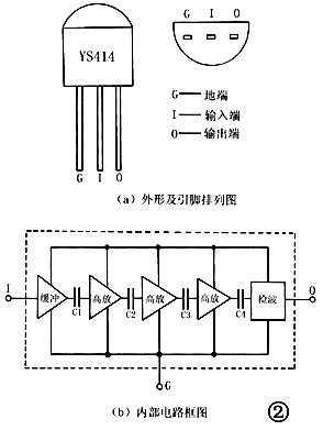
A (model YS414) is a special integrated circuit for direct-amplification detection radio. It uses TO-92 plastic packaging, and its packaging form is exactly the same as that of ordinary 9014 plastic packaging small power transistor. The shape and pin arrangement are shown in Figure 2. (A) as shown. Functions of each pin: G pin is a common ground terminal, I pin is an input terminal, and O pin is an output terminal. The YS414 integrated circuit is composed of 9 transistors, 16 resistors and 4 capacitors. Its functions include one-stage high-impedance input buffer, three-stage high-frequency amplification and one-stage detection. Its internal circuit block diagram is shown in Figure 2 (b). Show. The YS414 integrated circuit has the characteristics of high input impedance, large gain, low power consumption, few peripheral components, and no circuit debugging. It is very suitable for making miniature simple radios. 
When strong sunlight (or light) shines on the solar panel BP, the photovoltaic effect occurs on the surface of the BP, and a certain amount of power is output at both ends of the BP for the radio circuit to work. The magnetic antenna L and the variable capacitor C1 form a tuning loop. This is a parallel resonant circuit. Adjusting C1 can change the resonance frequency and play the role of selecting the desired station signal. The magnetic antenna L adopts a special magnetic rod for medium wave, which has high sensitivity, does not need an external antenna, and has a certain directivity when receiving a radio station. Because A has extremely high input impedance, the tuning loop can be directly connected to the input terminal I of A and into the ground through C2, without having to couple the input through the secondary coil like most radios. The radio signal sent into A, after multi-stage high-frequency amplification and detection by the internal circuit of A, outputs audio electrical signals from its O pin. R1 is the input stage bias resistor of A. It is connected to the positive pole of BP through the output load resistor R2 of A, which can also make A have automatic gain (AGC) control capability. If the signal received by the radio is strong, the operating current of A will increase, and the voltage drop on R2 will also increase, so that the operating voltage of A will drop, and the internal circuit gain will also decrease, resulting in a decrease in the output signal of A. Completed the function of automatic gain control. When R2 is too large, the AGC control is too strong, which will significantly reduce the circuit gain; when R2 is too small, the AGC control is too weak, which will cause the circuit to generate self-excited howling. C3 is a high-frequency bypass capacitor, which can filter out unnecessary high-frequency components contained in the detection signal; C3 selects the appropriate capacity, not only can get good sound quality, but also can get better automatic gain control characteristics.
The audio signal output from the O pin of A is sent to the potentiometer RP through the coupling capacitor C4 for volume adjustment, and then sent to the low-frequency amplifier circuit composed of VT1 and VT2 through the coupling capacitor C5 for power amplification, and finally the 8Ω earbud machine is pushed to play . VT1 constitutes a preamplifier, which amplifies the audio signal; VT2 constitutes an emitter follower, which converts the impedance of the 8Ω earphone machine connected to the jack XS to β times the current amplification factor of VT2 (ie β × 8Ω), Solve the problem that the high impedance output by VT1 cannot be directly matched with 8Ω earphones; the emitter follower also has the current amplification effect, which can make the earphones sound louder. R3 is the DC bias resistor of VT1. Since the base of VT2 is directly connected to the collector of VT1, the operating point of VT1 and VT2 can be adjusted by adjusting the resistance of R3; R4 is the negative feedback resistor of the emitter current of VT1, Its role is to further stabilize the operating point of VT1 and VT2.
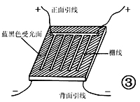
If the solar panel cannot be purchased at once, three 2CR32 silicon photovoltaic cells with a size of 10mm × 5mm, an open circuit voltage of 0.5 to 0.6V, and a short circuit current of ≥ 9mA can be replaced in series. The shape of this silicon photovoltaic cell is shown in Figure 3. Its light-receiving surface is blue-black, with several silver-white grid lines on it, leading out two wires as the positive electrode of the battery; the backlight surface is silver-white (tin-plated), leading out two The root wire serves as the negative electrode of the battery. 
A uses YS414 type micro radio special integrated circuit. Its main features: low working voltage, satisfactory normal operation at 1.3 ~ 1.5V; low power consumption, working current is only about 0.4mA when there is no signal; working frequency bandwidth, up to 150 ~ 3000kHz; strong amplification ability, power gain Up to 72dB, automatic gain control range up to 20dB. The internal circuits and functions of the YS414 are completely the same, but the integrated circuits of different manufacturers are: D7642, TA7642, CTC7642, YS7642, BS414, MK-484, 2N414, etc., which can be directly used interchangeably.
The transistors VT1 and VT2 use 9014 or 3DG8 silicon NPN low-power low-noise transistors, which requires the current amplification factor β value of VT1 to be between 40 and 150, and the VT2 β value to be between 20 and 60.
The magnetic antenna L needs to be wound by itself. The specific method: use φ0.15mm single-strand high-strength enameled wire, and wind a single layer on the φ5mm × 35mm medium wave magnetic rod with 82 turns. Pay attention when winding, in order to make the coil not loose, apply quick-drying glue (or white wax) to fix the beginning and end. For debugging convenience, it is best to use cardboard to make a coil skeleton before winding, so that the coil can move left and right on the magnetic bar.
C1 selects 5 ~ 200PF ultra-small sealed variable capacitors; C2, C3 and C6 all use CT1 type ceramic dielectric capacitors; C4 and C5 use CD11-10 type electrolytic capacitors. R1 ~ R5 all use RTX-1 / 8W carbon film resistors. RP selects WH15-1A type small synthetic carbon membrane potentiometer without switch. XS selects the two-core jack commonly used in CKX2-3.5 (φ3.5mm caliber) earbud headphones. The earphone adopts 8Ω low resistance earplug machine with CSX2-3.5 type (φ3.5mm) two-core plug.