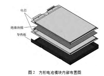
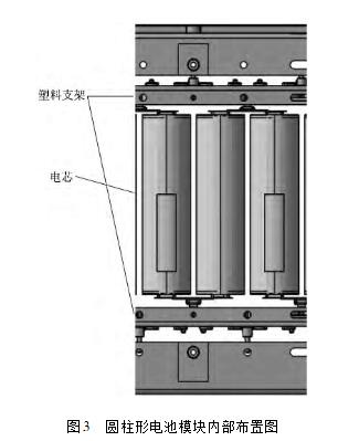
With the continuous improvement and development of power battery technology, the application scale of new energy vehicles has been greatly expanded. However, the power battery as a high-voltage energy storage system, its high voltage electrical insulation safety design can not be ignored. In order to solve the high-voltage electrical insulation safety problems faced by electric vehicles and ensure the safety of high-voltage electricity for electric vehicles, relevant industry standards in China have set forth clear requirements for the design and detection of high-voltage electrical circuits for electric vehicles. More detailed experimental testing procedures. In order to meet the high voltage safety requirements of electric vehicles, a systematic development process and management strategy for high voltage safety issues need to be established to ensure that the developed system has a sufficiently high insulation level and when high voltage power system failure occurs. Timely detection and judgment and automatic protection measures are taken to ensure the safety of the personnel in the vehicle. This article mainly introduces the high-voltage electrical insulation design ideas of the power battery system from the three levels of the battery core, module and system assembly. The common power battery system assembly consists of the following parts: (1) A battery module composed of batteries through a series of parallel connections; (2) Thermal management devices, including air cooling and water cooling; (3) Battery management unit, including functions for monitoring battery cell voltage and temperature, battery management, high-voltage measurement, and insulation detection; (4) Power distribution units, including relays, pre-charging circuits, etc.; (5) The battery system assembly shell and structural parts; (6) Other accessories. The functional blocks involved in the high-voltage electrical insulation design of the power battery system mainly include the insulation design of the battery core, the insulation design of the battery module, and the insulation design of the system assembly. The battery core is the basic energy storage unit of the power battery system. The insulation design of the battery core mainly considers: (1) Insulation between the positive and negative current collectors; (2) Insulation between the battery cell (assembly consisting of positive and negative current collectors and diaphragms) and the battery case; (3) Insulation between the positive and negative tabs and the housing. The insulation protection between positive and negative current collectors is mainly achieved by battery separators. Currently, commercial separator materials mainly include PP/PE/PP3 layer separators, PE single-layer separators, and ceramic separators based on PP/PE. The better mechanical properties and insulation properties of the separator ensure insulation between the positive and negative electrodes. Figure 1 shows a company's PP / PE / PP3 layer separator The insulation between the battery cell (the assembly of the positive and negative current collectors and the diaphragm) and the battery case is also mainly achieved through the diaphragm. After the positive and negative electrode current collectors are laminated or wound, usually 2 to 3 layers of separators are wound to ensure the insulation between the battery cells and the shell. For the flexible packaging cells, the outer shell is an aluminum-plastic composite film and the inner layer is a layer. Plastics also serve to reinforce insulation. The insulation design between the battery tabs and the housing is usually a layer of insulating material between the tabs and the housing. For example, the flexible packaging core adds a layer of insulating film with high mechanical strength and high temperature resistance between the tabs and the shell; an insulating gasket is added between the pole and the shell to ensure the insulation performance. The process quality control in the manufacturing process of batteries is very important, including the cleanliness of the environment, the reliability and accuracy of the operation of machinery and equipment, the determination of key quality points, and the detection methods. The insulation design of the battery module mainly includes the insulation protection between the cells, and the insulation protection between the cells and the metal structure of the module. The specific design is related to the structure of the module and the cooling method. The following are examples of two different shapes of cells and cooling methods. (1) The square type soft pack core adopts the liquid-cooled insulation design. The heat generated by the cell is first transferred to the heat-conducting plate in contact with the cell, then to the cooling plate in contact with the heat-conducting plate, and then out of the cell system through the circulating cooling liquid inside the cooling plate. In this example, a liquid-cooled battery module is used. One side of the cell is in contact with the heat conducting plate, and the other side is in contact with other cells. In order to ensure the isolation between the internal batteries of the battery module, an insulating gasket is added between the battery core and the battery core. The commonly used insulating material such as the insulating foam not only plays the role of insulation between the batteries, but also can Plays buffer and module length control. On the contact side of the cell and the heat conducting plate, the insulating mode is that a layer of thermally conductive insulating paint is applied on the surface of the heat conducting plate to ensure the insulation performance of the module. Figure 2 shows a design scheme for the internal insulation of a square battery module, using a heat-conducting plate with an insulating paint coating. The cell and the cell are separated by insulating foam. (2) Cylindrical batteries adopt air-cooled insulation design. The heat generated by the battery system is forced into the cold air through the air inlet, and is discharged from the air outlet after heat exchange with the surface of the battery core to achieve the cooling effect. Compared with the liquid-cooled module design, the air-cooled module insulation design is relatively simple, mainly due to sufficient clearance between the batteries to ensure that the cooling wind can pass through, reducing the insulation protection design between the batteries and the batteries. For the air-cooled module insulation design, the focus is on the bracket selection of fixed batteries inside the battery module. Usually, a plastic bracket with a certain mechanical strength is selected to meet the requirements of insulation protection on the one hand, and on the other hand to ensure that there is a cooling gas between the batteries. Enough clearance. FIG. 3 is a schematic structural diagram of a cylindrical battery module. There is a sufficient gap between the battery cores to ensure insulation, and a plastic bracket is used to further ensure the insulation performance of the module. The insulation design of the battery system assembly level mainly considers the insulation mode when the module is installed and fixed. For the liquid-cooled battery system, the heat of the module is taken away through the cooling plate with the cooling circuit, but considering the insulation requirements, it is usually designed in the battery module and Between the cooling plates, a layer of heat-conducting glue and insulation mats are added to improve the heat-conducting efficiency while taking into account the insulation performance. The commonly-used heat-conducting insulation mats are shown in FIG. 4 . For the air-cooled system, since the interior of the module often uses plastic brackets, there is a certain distance between the batteries and ground clearance, so the insulation design of the battery module is relatively easy. In addition, the system insulation design also needs to consider the sealing performance of the system. This is mainly because water or water vapor entering the battery pack will cause insulation failure inside the battery pack. Usually, the seal of the battery pack mainly considers the sealing performance of the connector, the sealing bolt design through the shell, and the seal design between the upper and lower lids. In particular, the seal design between the upper and lower lids is the most critical. The general design is to fold the upper lid and add O-rings between the upper and lower lids, or to increase the seal gasket between the upper and lower lids to ensure the system's Sealing performance. For air-cooled battery systems, the humidity of the cooling air intake must also be taken into consideration. Air conditioning air is usually introduced from the passenger compartment to ensure the temperature and humidity.
Antenk's High Definition Multimedia Interface (HDMI) connectors and cable assemblies are a series of products that provide an uncompressed digital link between video and audio in a single digital interface connection. Typically they are used with digital versatile (DVD) players, digital television (DVI), set top boxes and other audiovidual devices to consolidate interfaces and eliminate multiple cable assemblies. Adam Tech's HDMI series are small, easy to to use interconnects that can carry up to 5 Gbps of combined video and audio in a single connector/cable.
HDMI Connector Overview
HDMI Connector Types
Compact and user-friendly design
Hdmi Connectors,Hdmi Type Connector,Mini Hdmi Connector,Micro HDMI Connectors,Card Edge Hdmi Connector,HDMI Connector,Mini HDMI Connector,Micro HDMI Connector ShenZhen Antenk Electronics Co,Ltd , https://www.antenkelec.com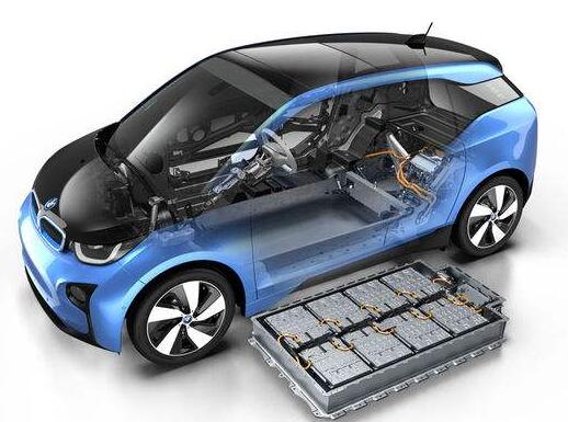


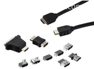
High Definition Multimedia Interface (HDMI) connector and cable assemblies deliver the highest quality, high-definition content by providing an uncompressed digital connection from any audio/video source to an audio and/or video monitor over a single cable. The single interface of the Antenk HDMI connector makes it economical and easy to use as it combines both video and multi-channel audio into a single-port connection, eliminating the cost, complexity, and confusion of multiple cables used in A/V systems.
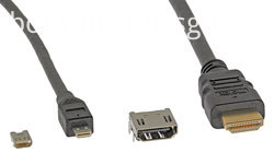
Micro HDMI connectors offer all the advantages of the HDMI standard 1.4 specification and are half the size of the industry Mini HDMI connector. Antenk`s Micro HDMI features a miniature footprint and low-profile height, which offers significant space savings, delivering equivalent mechanical strength and electrical characteristics.
Micro HDMI cable assemblies feature a stylish and compact overmold design and are available in a variety of customizable cable lengths.
Standard HDMI (HDMI Type A)
Extended Pin HDMI (HDMI Type B)
Mini HDMI (HDMI Type C)
Micro HDMI (HDMI Type D)
HDMI Connector Features and Benefits
Meets consumer equipment needs
Triad signal layout
Low impedance mismatch
Satisfy HDMI 1.4 Specification mechanical and electrical requirements
Customers enjoy all features and benefits of the HDMI 1.4 Specification
Friction lock on receptacle shell
Offers excellent retention force and tactile feel when mating
5 Gbps
Carries uncompressed audio and video in a single cable
Fully shielded connector
EMI/RFI protection
5,000 mating cycles for receptacles
Meets durability requirements for mobile applications
HDMI Connector Applications
Automotive
GPS
Commercial Vehicle
GPS
Consumer
DVD Players/Recorders
Digital camera
LCD and TV panel
Satellite Boxes
Televisions
Video / DVD products
Video games
Smart Phones and Mobile Devices
Smartphones