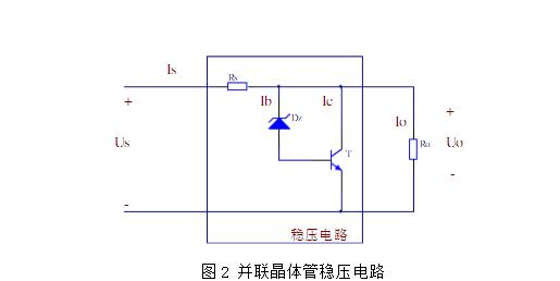
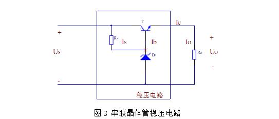
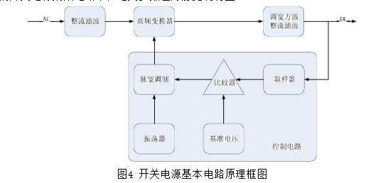
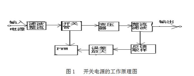
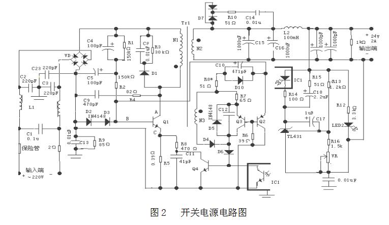
Zener diodes, also known as Zener diodes, are semiconductor devices that have a very high resistance up to a critical reverse breakdown voltage. At this critical breakdown point, the reverse resistance decreases to a very small value. In this low resistance region, although the current flowing through the diode changes greatly, the voltage across it changes very little, and this phenomenon is repeated. Very good, so as to play a role in voltage regulation. Because of this characteristic, Zener diodes are mainly used as voltage regulators or voltage reference elements. Figure 1 is a Zener diode regulator circuit consisting of current-limiting resistor Rs and Zener diode Dz. Us is the unregulated input DC voltage, U. For the regulated DC voltage, Rs is the current limiting protection resistor of Dz, and it also functions as a voltage regulator. D2 is a Zener diode and R is a load resistor. Its working principle is: This circuit mainly uses the voltage stabilizing characteristic of the zener diode, that is, the voltage drop across the two ends of the Dz reverse conduction remains basically unchanged. When Us increases, the current on Rs increases, but U increases. That is, the voltage across D remains constant, so that the increase of Us all falls on Rs to maintain U. No change, and vice versa. In practical applications, the characteristics of R and D2 play a key role in the entire regulation process. The operating range of this voltage regulator circuit is limited by the maximum power consumption of the regulator, Iz can not exceed a certain value. The key is: at Us, R and U. For all given conditions, the Rs value should be selected to ensure that the steady-state current Iz and the allowable power dissipation of the regulator do not exceed the specified maximum value when the input voltage is at the maximum Usmax; when the input voltage is at the minimum value, It is guaranteed that Iz is not lower than the minimum stable current. A transistor is a solid-state semiconductor device that can be used for detection, rectification, amplification, switching, regulation, signal modulation, and many other functions. As a variable switch, the transistor controls the outflow based on the input voltage, so the transistor can be used as a current switch. Figure 2 shows the shunt transistor voltage regulator circuit. Where T is the regulator tube, D2 is the reference regulator, and Rs is the current limiting resistor of Dz, R. Is the load. The output voltage of this voltage stabilizing circuit is approximately equal to the voltage stabilizing value of the voltage regulator tube Dz (in reality, the voltage of the T-transmitting junction is added. Generally, the voltage of the transistor is 0.3V, and the voltage of the silicon tube is 0.7V). This is because when the power supply is operating, the T-emitter junction is on, the emitter voltage is connected with the base voltage, and the base voltage is stabilized at a fixed value by Dz. This circuit can be regarded as T to amplify the voltage regulation effect of Dz by a factor of B, equivalent to connecting a regulator with a voltage regulation value of Dz and a voltage regulation effect of B times D2. Shunt voltage regulator circuit voltage regulator performance has improved, the circuit is not complicated, its advantages are: overload self-protection performance, output circuit breaker will not be damaged when the adjustment; when the load changes, the voltage regulator performance is better; for instantaneous changes Better adaptability. However, the shunt regulator circuit also has a big drawback: it has low efficiency, and especially when it is lightly loaded, electric energy is almost entirely consumed in the current limiting resistor and the adjustment tube; the output voltage adjustment range is very small; the stability is not easy to do very high. These inherent shortcomings are difficult to improve, so the current widespread use of series regulator circuits. Figure 3 shows a simple series-transistor regulator circuit. Adjust the tube T and load resistance R. In series, when the output voltage of the circuit fluctuates due to changes in power supply or power consumption, it can be adjusted in time to maintain the output voltage at a substantially constant level, so it is referred to as an adjustment tube. The regulator tube Dz provides a reference voltage for the regulator tube so that the base potential of the regulator tube does not change. R. It is the protection resistor of D2 that limits the current through D2 and acts as a protection regulator. The circuit voltage regulation process is this: If the input voltage Us increases, the output voltage U is made. When increasing, because the U. = U. is fixed and fixed, the voltage Uo = UU between adjusting the base shooting set will be reduced, the base current I will be reduced. With this decrease, the tube pressure drop U. increases with it, which cancels out the part where Us increases to make U. Basically stable. If the load current I. Increase the output voltage U. When reduced, due to U. Fixed, U" will increase, U. Decrease, also make U the same. Basically stable. From the analysis above, we can see that the adjustment tube is like an automatic variable resistance: when the output voltage increases, its “resistance†increases, sharing the large voltage; when the output voltage decreases, Its "resistance" is reduced, making up for the small voltage. In either case, the circuit keeps outputting a stable voltage. This voltage regulator circuit can also output a large current, and the output resistance is low, the voltage regulation performance is good; the circuit is also easy to make, but it also has the disadvantages of the output voltage is not adjustable. Radiator, the volume and weight are greatly reduced, with the advantages of small size and high efficiency. This switch type circuit has been widely used in various electronic devices. There are two types of switch-mode regulated power supply control methods: adjustable-width modulation and frequency-modulation. In actual applications, the wide-ranging type is used more often. Most of the switching power supply ICs currently developed and used are also Pulse width modulation type. Although the linear regulated power supply based on the above linear voltage stabilizing circuit has a simple circuit structure and reliable operation, it has a low efficiency (only 30%-50%), a large volume, a large consumption of copper and iron, a high operating temperature, and a small adjustment range. Other disadvantages. In order to solve the shortcomings of the linear power supply with high power consumption, a switch-mode power supply was developed. Switching regulator switching rate of up to 60% ~ 85% or more, and can save the power frequency transformer and a huge switching power supply, the basic circuit diagram shown in Figure 4. After the AC voltage is rectified and filtered by the rectifying circuit and the filter circuit, it becomes a DC voltage with a certain pulsating component. The voltage enters the high frequency converter and is converted into a square wave of a desired voltage value, and finally the square wave voltage is rectified. The filter becomes the required DC voltage. The control circuit is a pulse width modulator, which is mainly composed of a sampler, a comparator, an oscillator, a pulse width modulation, and a reference voltage. This part of the circuit has now been integrated into a variety of integrated circuits for switching power supplies. The control circuit is used to adjust the switching time ratio of the high-frequency switching element so as to achieve the purpose of stabilizing the output voltage. Commonly used switching control methods; self-excited switching regulators, pulse width modulation switching regulators, and DC switching switching regulators. The switching regulator circuit has a small size and high conversion efficiency, but the control circuit is more complicated. With the rapid development of self-shutdown power electronic devices and power integrated circuits, switching power supplies have become more and more widely used. Self-excited DC voltage regulator source has advantages of small size, light weight, high efficiency, strong adaptability to voltage and frequency changes of the power grid, long output voltage retention, and favorable for computer information protection, and is widely used in electronic computers. Leading various terminal equipments and communication equipments are the principle analysis of a self-oscillating DC stabilized power supply in the electronic information industry today. The working principle of the switching power supply is shown in Figure 1. The input voltage is AC220v, and the 50Hz AC is filtered and then rectified by the rectifier bridge to become DC. The high-frequency transformer is once turned on and off by the switch in the control circuit. The test produces low-voltage high-frequency voltages that are coupled to secondary measurements via low-power high-frequency transformers, and then rectified and filtered to obtain a DC voltage output. In order to stabilize the output voltage, TL431 sampling was used to amplify the error by optical coupling, and the PWM was used to control the turn-on and turn-off time (ie, duty cycle) of the switch, so that the output voltage remained stable. Switching power supply circuit diagram shown in Figure 2. In this power conversion circuit, a single-ended flyback converter is used because the core of its high frequency transformer only operates in the first quadrant. According to the transformer's secondary side switching rectifier = pole wiring different, single-ended converter can be divided into two types: forward and flyback. The switch state of the primary side main power switch tube and the secondary side rectifier tube is opposite (the switch tube is on, the secondary side rectifier is the pole tube cut off) and is called a single-ended flyback type. When the primary side is applied to the high-level excitation pulse to make Q1 conductive, the primary side of the DC input high frequency transformer is at both ends of the high-frequency transformer, since the secondary side is. The negative is positive and the rectifier is turned off. When the driving pulse is low, Q1 is turned off. The polarity of both ends of the primary is reversed, so that both ends of the secondary winding become positive and negative, and the rectifier diode is positive. The wizard opens, after which the magnetic energy of the secondary side of the transformer is released to the load. Therefore, the single-ended flyback converter only stores energy when the primary side Q1 is turned on. When it is turned off, it releases the load to the load. Therefore, the high-frequency transformer not only functions as a variable voltage isolation but also an inductance energy storage element during the switching process. The EMI filter connected to the input of the AC power supply consists of common mode chokes L1, C2, and C3. The midpoints of C2 and C3 should be grounded to suppress common-mode interference. C1 is used to filter, filter out the serial mode interference, and the capacitance is large. In view of the instant when the BU508A switch is turned off, the leakage inductance of the high-frequency transformer will generate a spike voltage. Using C8, R3, and D1 as a clamping circuit, the function of C9 is to filter the spike voltage of the collector of the switch tube and determine the automatic restart. Frequency, C9 and R4 together to compensate the control loop, while C9 and R4 also play the role of the original rapid reset, can effectively protect the switch tube from being damaged. 1, switch power switch control part The core of the switching power supply is the switch control part. The main working process is to control the time for the main power switch tube Q1 to turn on and off (ie, the size of the duty cycle) through the voltages of points B and C in FIG. 2 . When Q1 is turned off, point A is at a high level, C5 discharges Q1, so that the potential at point B is rapidly increased, so that the base potential of the switching transistor Q1 is higher than that of the emitter, so that Q1 is saturated and turned on, and C5 is charged. The current at this time is the sum of the primary current of the transformer and the current when Q1 is on. Therefore, the value of the current flowing through R5 is large, the potential of point C increases, and the saturation conduction turns point A into a potential drop, and Q1 also ends. The role of D2 and D3 is to make the potential of point C not very high when Q1 is turned on, otherwise the discharge time of C5 is too long, so that Q1 turn-off time toff is too large, and Q1 turn-on time ton remains unchanged, so the frequency becomes low . If Q1 turns on C When the point elevation is too high, Q1 is turned off. At this time, D2 and D3 are conducting, and the potential at point C is reduced, so that the discharge time of C5 will be very short and will make Vbâ€Vc, so that toff is also small, and therefore Make the frequency very high. 2, PWM adjustment section When Q1 is on, the winding N2 is positive and negative, and C10 absorbs the peak voltage just after discharge, prevents the diode D10 from being damaged by the forward conduction, and D10 is conducting to make the potential of the B point rise, thereby allowing the Q1 to saturate and turn on faster. At the same time, Q2 is turned on, Q3 is turned on again, and the voltage at point B is decreased, and the primary coil current is reduced to the cutoff. At this time, the N2 side is positive and negative, D4 ​​and D5 are turned on, the Q4 base becomes a high potential, Q4 is turned on, the potential at the C point is lowered, and the cutoff time becomes shorter, while the TL431 feedback current makes the current flowing into the base of the Q4 It will decrease, the potential at point C will fall slowly, and the deadline will be longer. When Q1 is turned on, the TL431 feedback current determines the speed at which the C point potential rises to achieve regulation. C12 is used to protect Q3. In the off-time, the reverse peak voltage is too high and damages Q3. The feedback control is to compare the sampling voltage with the reference voltage and convert it into a current. Then the current is amplified to adjust ton and toff to control the duty cycle so as to achieve the purpose of voltage regulation. R12 is the minimum load of the output voltage to prevent the voltage from being too high when the load is unloaded, and is used to increase the voltage regulation rate at light loads. C17 can properly reduce the high-frequency gain of the error amplifier. The reference voltage of TL431 is compared with output voltage Vo, form error voltage in R14, make the diode of IC1 produce different electric current. R14 is the current limiting resistance of the IC1 diode. The frequency of error amplification should be determined by R13, R16, VR and C17. The RC absorption network composed of C14 and R10 can eliminate high-frequency self-oscillation and reduce RF interference. 3, high frequency converter section Because the power provided by the primary side of the high frequency transformer is proportional to the square and frequency of ton, and proportional to the square of the input primary side DC voltage, it is inversely proportional to the number of turns of the primary winding, if the consumption of the transformer is not taken into account, The energy conservation can obtain the secondary side power of the transformer, that is, the output power is independent of the number of transformer secondary windings and the load, and is determined only by the power provided by the primary side. Therefore, to obtain different output power, it is only necessary to change the power of the primary side of the high-frequency transformer. Changing ton has the greatest impact on the output power, but it should not be changed greatly due to the limitation of the magnetic flux reset condition. To change the DC voltage input on the primary side, you can only change the parameters such as the filter inductance and filter capacitance of the front circuit, and you can also Adding a potentiometer can also change the DC voltage, and the frequency is limited by the condition of the power switch itself. Therefore, it is a better method to change the number of windings in the primary winding. The winding width of the primary winding should not be too long, and it should be divided into multiple layers. The access of each layer should be controlled by a switch, requiring different number of winding turns. Into the different switches can be a good control of the power on the primary side, resulting in different output power. However, during the time of toff, the primary magnetic flux of the high-frequency transformer is to be reset, and the secondary magnetic flux is to be reset during the ton time. If the magnetic flux does not return to the beginning of the cycle at the end of the switching duty cycle, the transformer The magnetic flux in the core will gradually increase, causing the core to saturate and damage the power switch tube. To meet the magnetic flux reset condition of the single-ended converter, the time of Ton and Toff should be appropriate and not too long. Otherwise, the frequency of the switch tube will become low, and it will be related to the number of turns of the primary and secondary windings of the high-frequency transformer. .
Antenk DVI Series Digital Video Interface connectors are the standard digital interface for flat panels, video graphics cards, monitors and HDTV units. This series includes DVI-D (Digital), DVI-A (Analog) and DVI-I (Integrated Digital/Audio). Their unique crossing ground blades provide high speed performance at low cost. They are available in Straight or Right Angle PCB mount receptacles and mating male cable connectors. They support a data transfer rate of 4.95Gbps with a dielectric withstanding voltage of 500VAC. Each version features our specially designed contacts which improve signal performance and a zinc alloy shield that reduces electromagnetic interference (EMI).
Digital Visual Interface Cable Connectors
DVI ConnectorWith the advent of technologies such as DVD players, high-definition televisions, and even digital cable, the need for more advanced cables and connectors has increased. Digital Visual Interface (DVI) is one response to the growing need for interconnected systems, enabling digital systems to be connected to an array of displays. Yet DVI cables and connectors can also be complicated, and may lead to confusion between High Definition Multimedia Interface (HDMI) and DVI. Although the two systems have much in common, they service different niches of digital technology.
Digital Visual Interface
Older systems aren`t necessarily outdated systems. Although DVI preceded HDMI, it`s still widely used in both business and domestic settings. DVI connectors are designed to handle digital data transmission, incorporating three transmission channels in every connector link. The maximum bandwidth for data transfer is 165 megahertz, which is enough to relay up to 165 million pixels per second. Data is encoded for effective transfer, but a single link can handle around 4.95 gigabits per second of information. Double links can handle twice that amount.
Because a DVI cable carries information over a 165 megahertz bandwidth, complete digital resolution can be obtained. Using double link connectors increases the speed of transmission, but requires another cable. However, not many devices depend solely on a double link DVI, so this technolgy can be used on an as-desired basis.
Types of DVI Connectors
There are three general categories of DVI cable connectors: DVI-Digital (DVI-D), DVI-Integrated (DVI-I), and DVI-Analog (DVI-A). However, most connectors fall into one of the first two groups.
A standard DVI connector is 37 mm wide and has 24 pins, 12 of which are used for a single link connection. When analog is involved, four additional pins are needed to support the additional lines of an analog signal. It is not possible to cross from a digital source to an analog display or vice versa. In those instances, an integrated connector is probably the best option. There are five common types of DVI connectors.
DVI-I Single Link
This kind of connector has three rows, each with six pins. There are two contacts. Because the connector is integrated, it can be used with both analog and digital applications.
DVI-I Dual Link
A DVI-I dual link connector can also be used with both digital and analog applications, but is configured with more pins to accommodate a dual connection. There are three rows with eight pins each, as well as two contacts.
DVI-D Single Link
Specifically designed for digital applications, a DVI-D single link connector has three rows of six pins, and looks much like a DVI-I single link connector. However, a DVI-D connector has no contacts.
DVI-D Dual Link
Also made specifically for digital applications, a DVI-D dual link features more pins (three rows of eight) for dual connections. Like a DVI-D single link, a DVI-D dual link connector has no contacts.
DVI-A
This particular type of connector can only be used for analog applications, and has three rows of pins. One row has five pins, one has four pins, and the last row has three pins. Like single link connectors, a DVI-A link connector has two contacts.
Dvi Connector,Dvi Female Connector,Dvi Hdmi Connectors,Vga Dvi Connector,Digital Visual Interface Cable Connectors ShenZhen Antenk Electronics Co,Ltd , https://www.antenk.com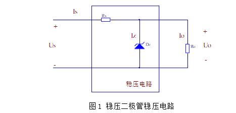

Typical Four DC Regulator Circuits 1, Zener Diode Regulators