Try to write something! CogniTIve Engine Technology.
How do you calculate track width in PCB?
The traces in the PCB are used to connect various components to various connectors. These traces can be identified as continuous paths of copper present on the surface of the circuit board. The trace width becomes critical because it directly affects the work of the PCB. In addition, increasing the current flowing through the PCB traces will generate a lot of heat. Monitoring the trace width also helps to minimize the heat build-up that normally occurs on the circuit board. The width of the conductor also determines the trace resistance that directly affects the current. 48Hours For 6Layer Pcb,Pcb Design Softwares,Printed Circuit Keyboard,Pcb Trace Width Calculator HAODA ELECTRONIC CO.,LIMITED , https://www.pcbhdi.com
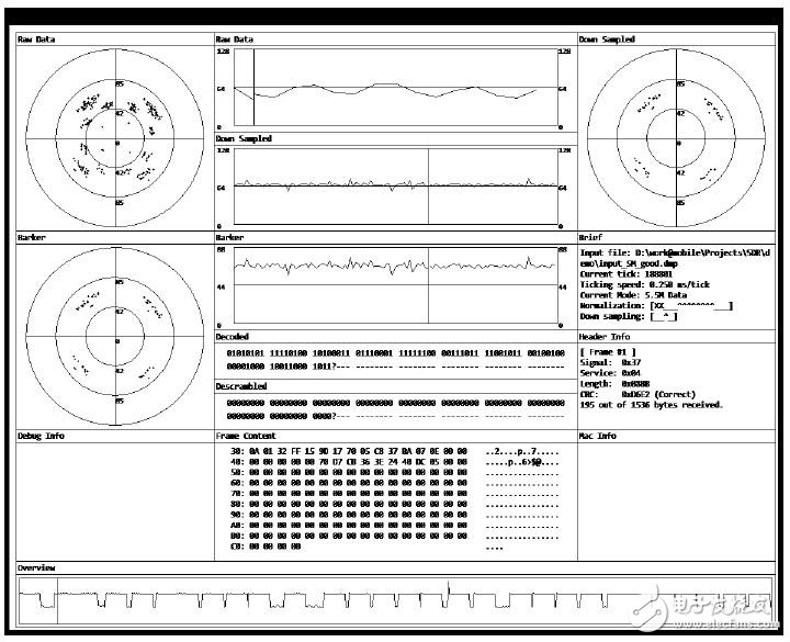
Cognitive Radio (CR) is an intelligent radio communication system that senses the surrounding electromagnetic environment, wireless channel characteristics, and user needs, and adaptively adjusts its internal configuration and optimizes it through reasoning and learning from past experience. System performance to adapt to changes in the environment and needs.
Partially reconfigurable (PR) is a technique for dynamically modifying logic blocks by downloading partial bit files while not interfering with other logic operations.
Many manufacturers choose the default trace width available, which may not be suitable for high frequency applications. Moreover, depending on the application, the trace width will vary, which will affect the current carrying capacity of the trace. Trace width is considered to be one of the most important design parameters in PCB design. It is important to determine sufficient trace width to ensure the quality and performance of the PCB. This also helps to ensure the safe transmission of current without overheating and damaging the circuit board.

We have developed an online tool for calculating the total minimum trace width. The amount of current and copper weight help determine the minimum trace width. We provide thicker conductor traces to meet higher current requirements. We also provide thicker copper weights to allow finer traces.
How to calculate trace width in PCB design
Important parameters
They are the correct trace widths for various factors that affect the selection. Some key factors include the thickness of the copper layer, the type of bottom or top layer, and the length of the track. A special design guide is prepared for the traces on the PCB. These design guidelines are prepared specifically for the inner layers of the circuit board. Heat does not easily escape through these inner layers.
Other factors such as dielectric height and dielectric constant (Dk) will also determine the trace width. We also consider other basic parameters, such as the inductance and capacitance of the trace, and the propagation delay. This allows us to also calculate the trace width accurately to a large extent. We also understand the need to improve the signal integrity of circuit signals. This helps us develop impedance calculators for single-ended and differential pair signals. In addition, maintaining proper signal integrity in the PCB can reduce losses such as copper loss and noise.

Key parameters of single-ended and differential pairs
Having said this, we usually recommend that customers choose larger traces to prevent disconnection, and at the same time there is more space on the PCB.
Establish the relationship between the current carrying capacity of the conductor and the trace width
The criticality of the trace width calculation also depends on the cross-sectional area of the PCB copper foil, the maximum current carrying capacity, and the constant temperature rise. In addition, parameters such as conductive material selection and current-carrying capacity vary according to the conductor type including the inner conductor and the outer conductor. We have defined the maximum current carrying capacity of the inner conductor as half of the outer conductor.
The cross-sectional area of the copper foil is proportional to the trace width. We can also say that the temperature rise and the maximum current-carrying capacity depend on the outer conductor and the inner conductor.

Due to various factors, the maximum current carrying capacity of the copper trace is usually different from the theoretical value. Some factors include the number of components, pads and vias. In addition, large transient surges can cause traces between pads to burn during the initial power supply or to implement order modifications on the traces.
In order to solve such complex problems, we tend to increase the trace width. However, there may be situations where a smaller trace width is required, so a solder mask can be applied on the trace. Solder masks are often applied to potentially burn out the PCB trace area. Solder paste can also be applied to Surface-Mount (SMT) &BGA Assembly programs. PCBA Manufacturing has also increased the current carrying capacity of the conductor with the help of reflow soldering.
In simple terms, it is best to calculate the current carrying capacity of the PCB trace to determine the precise trace width. However, other external factors, such as dust or contaminants, are also considered in the actual printed circuit manufacturing or assembly. Excessive pollution caused part of the trace to be broken.