OLED process introduction Indium tin oxide (ITO) substrate pretreatment (1) ITO surface flatness ITO is currently widely used in the manufacture of commercial display panels, which has the advantages of high transmittance, low resistivity and high work function. In general, ITO manufactured by RF sputtering is susceptible to poor process control factors, resulting in uneven surface, which in turn produces sharp substances or protrusions on the surface. In addition, the high temperature calcination and recrystallization process will also produce a protrusion layer of about 10 ~ 30nm on the surface. The paths formed between the fine particles of these uneven layers provide an opportunity for holes to be directed toward the cathode, and these intricate paths increase the leakage current. There are generally three ways to solve the effect of this surface layer. One is to increase the thickness of the hole injection layer and hole transport layer to reduce leakage current. This method is mostly used for PLED and OLED with thicker hole layer (~ 200nm). The second is to reprocess the ITO glass to make the surface smooth. The third is to use other coating methods to make the surface smoother. Cathode process In the high-resolution OLED panel, the fine cathode is separated from the cathode. The commonly used method is the mushroom structure approach, which is similar to the negative photoresist development technology of printing technology. In the process of negative photoresist development, many process variation factors will affect the quality and yield of the cathode. For example, bulk resistance, dielectric constant, high resolution, high Tg, low critical dimension (CD) loss, and proper adhesion interface with ITO or other organic layers.
Hybrid PCB Assembly = Hybrid Printed Circuit Board Assembly, which means the PCB Board need be mounted with SMT parts and THT parts. For such PCB Assembly job, SMT assembly will be done first, after checked well, then do THT assembly. Zhongfeng would manufacture the PCB boards follow the design file, source the components follow the BOM file and do the PCB assembly job follow the assembly drawing and the pick&place file. After PCB assembly done, the components would be mounted on the PCB boards tightly and connected each other through the copper circuits. We call such board as PCBA board or hybrid custom PCBA board.
Depends on the components assembly types, it have THT PCB assembly, SMT PCB Assembly , one sided SMT and THT PCB assembly, two sided SMT and THT PCB assembly.
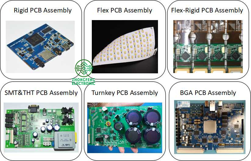
Depends on the PCB type, it have Rigid PCB Assembly , Flex PCB Assembly and Flex-Rigid PCB Assembly.
Also we would call some PCB assembly types as Prototype PCB Assembly, Mass PCB Assembly , Turnkey PCB Assembly, LED PCB Assembly and BGA PCB Assembly , etc.
With our 15years professional experience, we are available for all types of PCB assembly service from prototype to mass production, available for 01005, 0201, 0.3mm BGA, 0.3mm QFP.
PCB Assembly Capabilities
Quantity
1 pcs - 1,000,000 pcs
Assembly type
SMT, THT or Hybrid
Parts procurement
Full turnkey (ZhongFeng provide all components)
Partial turnkey ( Customer provide the main components and ZhongFeng provide the rest)
Kitted (Customer provide all components)
Component types
SMT 01005, 0201, BGA 0.3mm pitch, QFP 0.3mm pitch, etc.
Test
Visual Inspection, AOI, Custom testing, ICT, FCT, Test jig
PCB Assembly Products Show
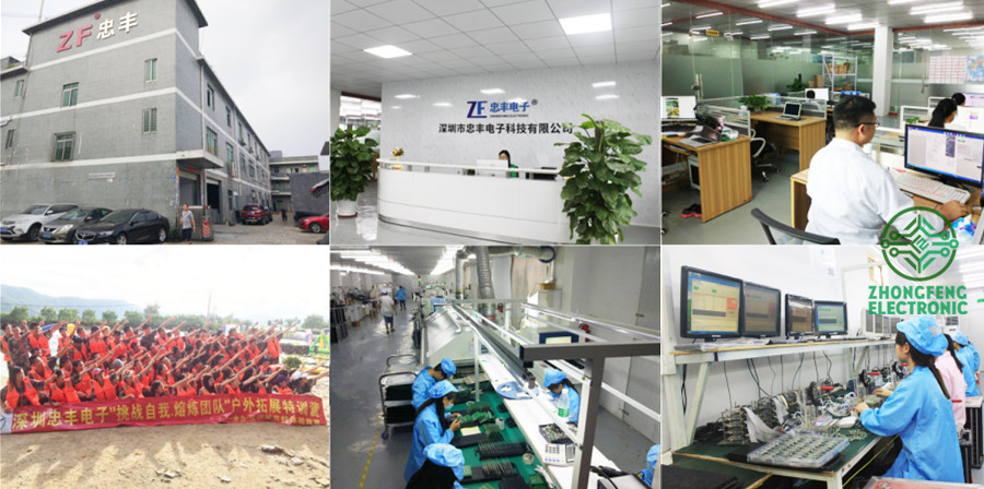
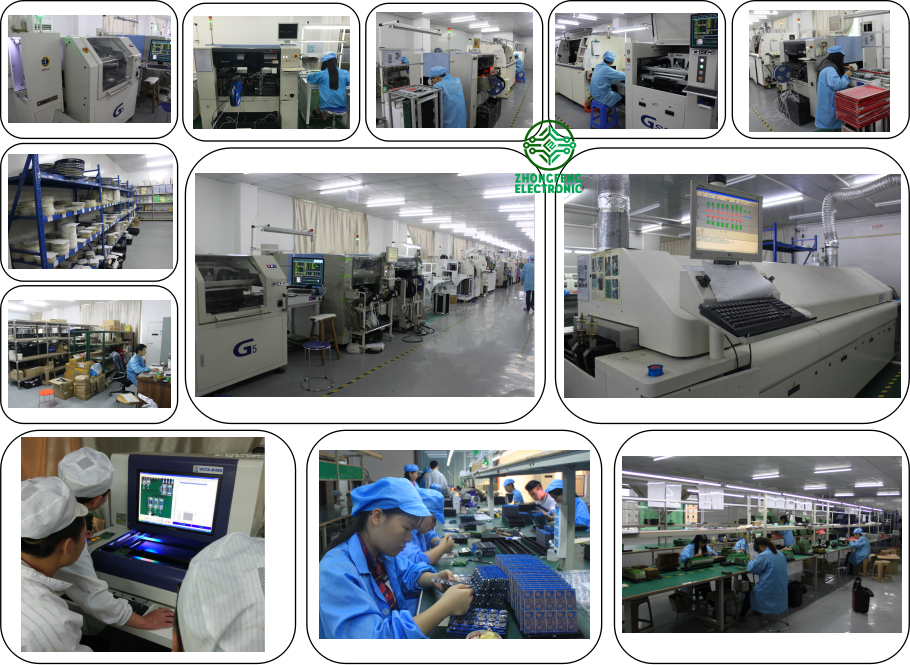
PCB SMT Assembly Factory Show
Hybrid PCB Assembly Hybrid PCB Assembly,Hybrid Integrated Circuit,Hybrid PCB Assembly Service,Hybrid Circuit Board Assembly ZhongFeng Electronic Technology Co., Limited , https://www.dopcba.com
(2) Increase of ITO work function When holes are injected into HIL from ITO, excessive potential energy difference will generate a Schottky barrier, making it difficult for holes to be injected, so how to reduce the potential energy difference of ITO / HIL interface becomes The focus of processing. Generally, we use the O2-Plasma method to increase the saturation of oxygen atoms in ITO to achieve the purpose of increasing the work function. After ITO is processed by O2-Plasma, the work function can be increased from 4.8eV to 5.2eV, which is very close to the work function of HIL.
The auxiliary electrode is added. Since the OLED is a current-driven component, when the external circuit is too long or too thin, a severe voltage gradient will be caused in the external circuit, so that the voltage that actually falls on the OLED component will drop, resulting in a reduction in the luminous intensity of the panel. Because the ITO resistance is too large (10 ohm / square), it is easy to cause unnecessary external power consumption. Adding an auxiliary electrode to reduce the voltage gradient has become a quick way to increase the luminous efficiency and reduce the driving voltage. Chromium (Cr: Chromium) metal is the most commonly used material for the auxiliary electrode, which has the advantages of good stability to environmental factors and greater selectivity to etchant. However, its resistance value is 2 ohm / square when the film layer is 100 nm, which is still too large in some applications, so it has a lower resistance value of aluminum (Al: Aluminum) metal (0.2 ohm / square) at the same thickness ) Becomes another better choice for auxiliary electrodes. However, the high activity of aluminum metal also makes it a problem of reliability. Therefore, multi-layer auxiliary metals have been proposed, such as: Cr / Al / Cr or Mo / Al / Mo, however, such processes increase the complexity and Cost, so the choice of auxiliary electrode material has become one of the focuses in the OLED process.
Encapsulation (1) The life cycle of water-absorbing materials is generally reduced by the influence of surrounding moisture and oxygen. There are two main sources of water vapor: one is penetration into the component through the external environment, and the other is the water vapor absorbed by each layer of material in the OLED process. In order to reduce the entry of water vapor into the components or to remove the water vapor absorbed by the process, the most commonly used substance is a water-absorbing material (Desiccant). Desiccant can use chemical adsorption or physical adsorption to capture freely moving water molecules to achieve the purpose of removing moisture in the module.
(2) Process and equipment development The packaging process flow is shown in Figure 4. In order to place the Desiccant on the cover plate and bond the cover plate to the substrate smoothly, the cavity needs to be filled in an inert gas in a vacuum environment, for example Nitrogen. It is worth noting that how to make the two parts of the cover plate and the substrate process more efficient, reduce the packaging process cost and reduce the packaging time to achieve the best mass production rate, has become the three major goals of packaging process and equipment technology development .


