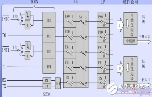
What is an interruption? It is to interrupt what is going on and to do something else. The MCU interrupt is when the MCU is executing the program, suddenly a button is pressed (generating an external interrupt), the MCU must deal with that button (interrupt response) to see what happened, after the button is processed Continue to come back to execute the program (return of the interrupt). The symbols, names, and conditions of the five interrupt sources are as follows. INT0: External Interrupt 0, introduced by the P3.2 port line, caused by a low or a falling edge. INT1: External Interrupt 1, introduced by the P3.3 port line, caused by a low or a falling edge. T0: Timer/Counter 0 interrupt, caused by T0 rollover. T1: Timer/Counter 1 interrupt, caused by T1 counting back to zero. TI/RI: Serial I/O interrupt, caused by the serial port after one frame of character transmission/reception. The block diagram of the entire interrupt system is shown in Figure 1 below. Figure 1 51 single chip interrupt system structure As shown in the figure, it consists of special function registers related to interrupts, interrupt entry, sequence query logic, etc., including 5 interrupt request sources, 4 registers IE, IP, ECON and SCON for interrupt control to control the interrupt class. The priority of interrupts, on, off, and various interrupt sources. (1) External interrupt request source: external interrupt 0 and 1, introduced via external pin, there are two pins on the MCU, the name is INT0, INT1, that is, P3.2, P3.3 foot. Four of the internal TCONs are related to external interrupts. IT0: INT0 trigger mode control bit, can be set and reset by software input, IT0=0, INT0 is low level trigger mode, IT0=1, INT0 is negative transition trigger mode. The difference between the two methods will be discussed later. IE0: INT0 interrupt request flag. When there is an external interrupt request, this will be set (this is done by hardware), and IE0 is cleared by hardware after the CPU responds to the interrupt. The use of IT1 and IE1 is the same as IT0 and IE0. (2) Internal interrupt request source TF0: Overflow interrupt flag of timer T0. When T0 count overflow occurs, TF0 is set by hardware. When the CPU responds to the interrupt, the hardware clears TF0 to 0. TF1: Similar to TF0. TI, RI: Serial port transmission and reception interrupts, explained in the serial port. Interrupt Enable Register IE In the MCS-51 interrupt system, the enable or disable of interrupts is controlled by the 8-bit Interrupt Enable Register IE, which is bit addressable on-chip. Where EA is the master switch, if it is equal to 0, then all interrupts are not allowed. The ES-serial port interrupt allows the ET1-Timeout 1 interrupt to allow the EX1-External Interrupt 1 interrupt enable. The ET0-Timer 0 interrupt allows the EX0-External Interrupt 0 interrupt to be enabled. If we want to set the allowable external interrupt 1, the timer 1 interrupt is allowed, the other is not allowed, then the IE can be EAX or 8CH, of course, we can also use the bit operation instruction SETBEA SETBET1SETBEX1 To achieve it. Wuxi Lerin New Energy Technology Co.,Ltd. , https://www.lerin-tech.com
