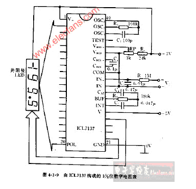
The 3,1 2-digit digital voltmeter circuit diagram voltmeter consisting of ICL7137 is an instrument for measuring voltage. The common voltmeter-voltmeter symbol: V, there is a permanent magnet in the sensitive galvanometer, and two in the galvanometer. A coil of wire is placed in series between the terminals, and the coil is placed in the magnetic field of the permanent magnet and connected to the pointer of the watch through the transmission. Most voltmeters are divided into two ranges. (0—3V) (0—15V), the voltmeter has three terminals, one negative terminal, two positive terminals, the positive pole of the voltmeter is connected to the positive pole of the circuit, and the negative pole is connected to the negative pole of the circuit. The voltmeter is a fairly large resistor and ideally considered to be an open circuit.
24v wall charger,24v dc adapter,24v ac dc adapter,24v switching adapter,100-240V AC to DC 24V 3A 72W Power Adapter,12W Ac Switching Power Adapter,24V 0.5A Power Supply For Led Lights Shenzhen Waweis Technology Co., Ltd. , https://www.waweispowerasdapter.com
Both the voltmeter and the ammeter are based on one principle. The greater the current produced by the magnetic effect of the current, the greater the magnetic force generated. The greater the swing of the pointer on the voltmeter, the larger the voltmeter has a magnet and a The wire coil, after passing the current, causes the coil to generate a magnetic field. When the coil is energized, it will rotate under the action of the magnet. This is the head part of the ammeter and the voltmeter. The current that this meter can pass is very small, and the voltage that can be withstand at both ends is also very small (certainly far less than 1V, may only be zero or several volts or less). In order to measure the voltage in the actual circuit, it is necessary to give This voltmeter is connected in series with a relatively large resistor to make a voltmeter. 
