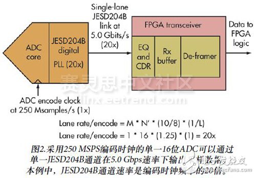
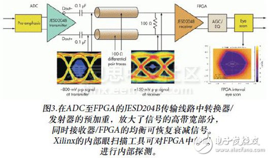
As more analog-to-digital converters (ADCs) and digital-to-analog converters (DACs) support the latest JESD204B serial interface standard, the best interface between FPGAs and these analog products has emerged. FPGA vendors have supported Gigabit Serial/Deserial (SERDES) transceivers for many years. However, in the past, most ADCs and DACs could not be configured through these high-speed serial interfaces, meaning that FPGAs and converters could not interface with any common standard, using high serial-deserial (SERDES) bandwidth. The JESD204B interface was developed to support the growing bandwidth requirements of higher speed converters to fill this gap. As a third-generation serial data link standard, the JESD204B offers a higher maximum channel rate (up to 12.5 Gbps per channel), supporting the determination of delay and harmonic frame clocks. The interface easily transfers large amounts of data to be processed with a scalable, high-performance converter that is compatible with open market FPGA solutions. Most signal processing systems are first defined by their analog or RF frequency, dynamic range, and sampling rate to establish converter selection criteria. However, when data processing is matched with the FPGA, the consideration of the digital interface of the converter cannot be ignored anyway. As long as you understand the new JESD204B interface and keep in mind some advanced considerations, it is not difficult to choose the right JESD204B converter for your FPGA. Here are some frequently asked questions and answers about matching JES204B converters to FPGAs. Highlight the key points when using this new serial interface for converter design. Often, the designer actually asks the transceiver line rate that the FPGA needs to support in the JESD204B and converter interface applications. The transceiver is a high-speed serial interface in FGPA that can send or receive data and recover embedded clocks. The transceiver acts primarily as a high-speed data port, independent of function. But if you have the right firmware around them, they can provide digital support for many different interface protocols. For example, an FPGA transceiver can act as a parallel to serial transmitter or a serial to parallel receiver (Figure 1). For high-speed serial interfaces such as the JESD204B, the FPGA transceiver can function in two ways in the system. When the FPGA supports ADC external data downstream acquisition, it acts as a serial data receiver. When the transceiver receives data, it converts the high-speed serial stream into parallel frame data, further downstream processing in the FPGA. Adaptive gain control (AGC), equalization (EQ), and clock/data recovery (CDR) functions are required before converting data from serial format to parallel format. When the FPGA is delivering data to the DAC, it performs the transmitter function. As a transmitter, it will form frame data and be sent serially through a high speed interface. The pre-emphasis function (subsequent talks) amplifies the signal to make the transmitted data as complete as possible. Typically, the system's analog sample rate or update rate will indirectly determine the FPGA transceiver line rate on the JESD204B interface. The converter's clock or code rate is achieved by phase-locked loop (PLL) multiplier to achieve the JESD204B bit rate. The maximum line rate supported by the converter may not be required by the system, but should be adjusted by a known frequency multiplier. Figure 2 shows a single (M = 1) 16-bit (N' = 16) ADC with a 250 MSPS encoded clock that transmits data over a single JESD204B channel (L = 1) at 20 times the encoding clock rate (5 Gbps) . This operation includes an 8-bit/10-bit encoding overhead. The converter uses a different encoding clock than 250 MSPS, and the output channel rate is adjusted up or down to 20 times the current encoding clock rate. The JESD204B specification lists standards that meet the 20cm transmission line requirements. The physical characteristics of printed circuit board (PCB) trace materials dominate the attenuation that the signal encounters during transmission. However, active channel compensation techniques on most converters and FPGAs help improve link performance. The converter or FPGA transmitter output can increase the high bandwidth portion of the serial data while keeping the low bandwidth portion unchanged. This technique is known as pre-emphasis. Since low-pass signal attenuation first affects the high-bandwidth portion of the signal (rise and fall times), pre-emphasis helps increase the serial signal transmission distance. As with the receiver, the DAC or FPGA can provide automatic gain control and EQ to the input signal to increase the high frequency portion of the visible signal at the end of the transmission line. This technology typically has different gain and equalizer settings to help optimize data recovery based on system requirements. In addition to the equalization phase, Xilinx also provides an internal probing tool to visualize the data eye seen in the FPGA (Figure 3). To reduce the computational burden of FPGAs, some converter vendors have added digital processing to the entire converter solution. Some signal processing systems only need to use the filtered signal bandwidth portion. Transmitting and processing full bandwidth data sent to or from the FPGA is an overhead burden and is completely unnecessary. For example, the ADC implements digital down conversion (DDC), which effectively sends the first of every four analog samples to the FPGA. Digitally filtered data can use a lower data rate on the JESD204B interface and eliminate the need to configure the DDC clock on the FPGA. In contrast, the DAC interpolation function allows data to be sent from the FPGA to the DAC using only 1/4 of the data rate and digital interpolation of the remaining three of the four samples using a complex algorithm. The DAC interpolation method can only transmit a subset of the data and then fully assemble in the converter before outputting in analog format. Regardless of whether your link uses a single converter or multiple converters, the number of JESD204B channels that the converter interfaces to the FPGA interface is directly related to line rate, converter sample rate, and packet efficiency. Although the converter can provide four JESD204B channels, a system operating at a 1/2 maximum converter sampling rate may only require two channels. Each converter can implement different JESD204B channel counts, speeds, and data packets depending on the design. Check the converter data sheet to see what options are best for your application. Yes, this can be done as long as the number of channels supported by the FPGA is sufficient for the application. One of the main difficulties of multi-ADC systems is the alignment of sampled signals that have different delay times from analog to digital sampling. The JESD204B interface has a corresponding specification for the system reference signal (SYSREF). This helps create a defined delay time for each converter in the system, providing a solution for multi-converter synchronization. Since data frames are used on the JESD204B, data frames from multiple ADCs can be aligned in the post-processing steps of the FPGA. This corrects the delay mismatch between the converter and the FPGA transceiver. Similarly, the FPGA can frame the data before sending it to multiple DACs. This is in consideration of systems that need to synchronize multiple converters with a single or several FPGAs. Some converter vendors also provide additional synchronization capabilities beyond the official specifications for labeling specific samples. If your system requires multiple converters to synchronize, minimize the number of JESD204B channels connected to the converter and choose the FPGA with the highest performance. The JESD204B protocol stipulates that sampling data from multiple ADCs with different delays needs to be aligned to achieve synchronization in the FPGA. Figure 4 shows how the frame data or tagged samples from multiple links are realigned for synchronization processing. The JESD204B interface uses an embedded clock for high-speed serial data transmission. However, FPGAs require a slower reference clock as the primary clock to process the data. The speed of the FPGA family and the product determines this function. It is important to consider which method the FPGA needs to handle the converter data. For example, an application that collects periodic discrete data sets to memory, and applications that continuously process and send data at full speed, which may require different FPGA fabric speeds. Another indication of this question may be "I should I get the intellectual property (IP) of the JESD204B firmware from the FPGA manufacturer or develop it myself?" FPGA vendors such as Xilinx offer autonomous IP solutions for JESD204, JESD204A and JESD204B interfaces. Program. These solutions may vary slightly depending on the product generation of JESD204 and the transceiver speed of the FPGA product. Be sure to complete the converter selection as early as possible to clarify the FPGA form and associated IP that you need to use in your system. You should consider which FPGA vendor's product to use, which generation of JESD204, the FPGA family and model, and the technical code writing capabilities you need to implement IP internally. Some JESD204B converters may require a special extra application layer, or a code "wrapper" around IP, which is basically a unique set of firmware instructions. If this is the case, the converter vendor should confirm and provide the application code to connect to the FPGA IP. The contents of the JESD204B converter link should be listed in the data sheet. Some converter manufacturers have also developed a battery that performs thorough verification tests between their devices and FPGA firmware to demonstrate product stability. Some FPGA products support transceivers that have gaps during operation that cannot be used with known frequency ranges. This makes the JESD204B channel frequency planning a bit more complicated, but still within the controllable range. Frequency planning for the converter sampling rate and the JESD204B channel rate is key to keeping the frequency away from the transceiver gap. Most converter systems typically have a fixed frequency of use. There are only a handful of situations where it is necessary to support occasional unique applications. Depending on the fixed sample rate of the system converter and the previously discussed JESD204B rate multiplier, the system designer can determine if the transceiver frequency gap is causing problems for the system. Even if you find that the desired channel frequency is just within the gap, you should check the converter data sheet to see if there are other options for adjusting the channel rate. For example, you can change some of the other variables in the equation, such as the number of channels or JESD204B to use resolution information to increase or decrease the frequency curve to avoid the transceiver frequency gap. The new converters and FPGA interfaces such as the JESD204B are complex, making them difficult to handle, and the need to decompose critical systems is critical. The sampling rate and the JESD204B channel rate multiplier must be known. Planning and selecting the right FGPA product based on factors such as IP support, transceiver count, transceiver speed, and frequency gap will help you choose the right converter. The process of selecting the right JESD204B converter can be simplified by focusing on some advanced standards that match the FPGA. Outdoor Rental Stage Events Led Display Outdoor Rental Stage Events Led Display,Outdoor Concert Stage Background Wall,Outdoor Stage Rental Led Screen,Events Venue Led Screen System Guangzhou Cheng Wen Photoelectric Technology Co., Ltd. , https://www.cwledwall.com


