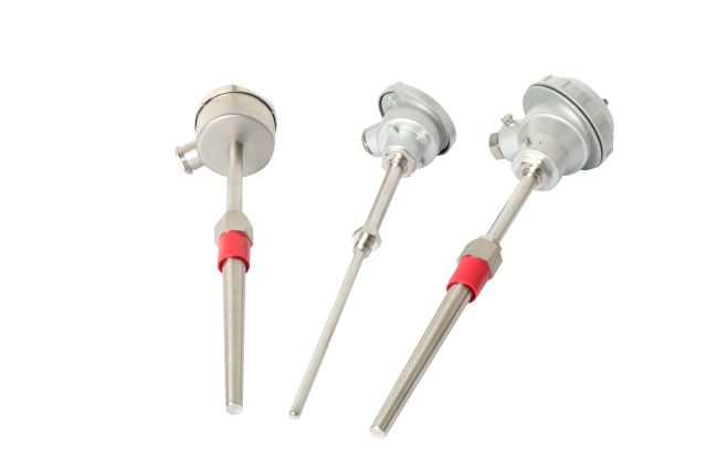
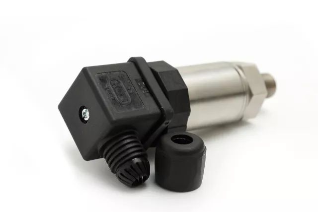
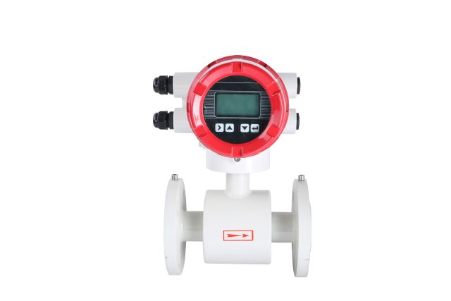
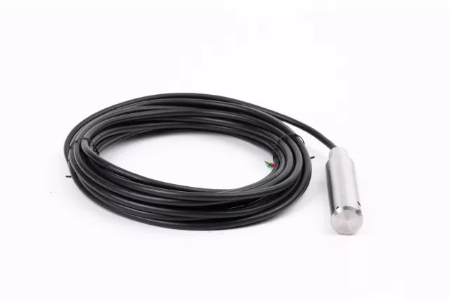
Regardless of the type of instrument failure, we must first understand the production process and conditions of the installation location of the instrument, and understand the structural characteristics and performance of the instrument itself; before repairs, we must combine with the technicians to analyze and determine the real cause of the instrument failure ; At the same time, it is necessary to understand whether the instrument is accompanied by adjustment and interlocking functions, and the process should be kept as stable as possible during the maintenance process. Today, I will mainly talk about the failure analysis of temperature, pressure, flow, and liquid level field instruments. temperature â‘ : Sudden increase in temperature: This fault is mostly caused by thermal resistance (thermocouple) open circuit, loose wiring terminals, (compensation) wire break, temperature failure, etc. At this time, it is necessary to understand the location of the temperature and the wiring layout. The resistance (millivolt) file of the multimeter can be quickly found out by measuring several sets of data at different positions. â‘¡: Sudden decrease in temperature: This fault is mostly caused by thermocouple or thermal resistance short circuit, wire short circuit and temperature failure. Start with the weak points that are prone to failure, such as wiring ports and wire turns, and investigate them one by one. The temperature rises on site, but the general control indication remains unchanged, mostly due to liquid (water) with a lower boiling point at the measuring element. â‘¢: Large fluctuations or rapid fluctuations in temperature: At this time, the process operation should be mainly checked (inspection and adjustment systems involved in adjustment). pressure â‘ : The pressure suddenly decreases or increases or the indication curve does not change: At this time, check the transmitter pressure system, check whether the root valve is blocked, whether the pressure tube is unblocked, whether there is abnormal medium in the pressure tube, or the drain wire is blocked And whether the drain valve is leaking, etc. Medium freezing in winter is also a common phenomenon. The transmitter itself is unlikely to fail. â‘¡: Large pressure fluctuations: This situation must first be combined with the craftsman, usually caused by improper operation. The parameters involved in the adjustment should mainly check the adjustment system. flow â‘ : The minimum flow indication value: Generally caused by the following reasons: the detection element is damaged (the zero point is too low.; the display is faulty; the line is short-circuited or open; the positive pressure chamber is blocked or leaked; the system pressure is low; the parameters involved in the adjustment should be checked and adjusted , Regulating valve and solenoid valve. â‘¡: The maximum flow indication: the main reason is the blocking or leakage of the negative pressure chamber pressure system. It is unlikely that the transmitter needs to be adjusted. â‘¢: Large flow fluctuations: flow parameters do not participate in the adjustment, generally due to process reasons; those involved in the adjustment, can check the PID parameters of the regulator; with the parameters of the isolation tank, check whether there are bubbles in the pressure pipe, and the positive and negative pressure pipes Whether the liquid is the same height. Liquid level â‘ : The liquid level suddenly increases: Mainly check whether the pressure system of the negative pressure chamber of the transmitter is blocked, leaked, gas collected, lack of liquid, etc. The specific method of filling liquid is: stop the watch first in the order of stopping the watch; close the positive and negative pressure root valve; open the positive and negative pressure drain valve to relieve pressure; open the double-chamber balance container filling plug; open the positive and negative pressure chamber drain plug; At this time, the liquid level indication is the maximum. Close the drain valve; close the drain plug in the positive and negative pressure chamber; slowly pour the same medium into the double-chamber balance container, then slightly open the drain plug to exhaust; until it is full, open the positive pressure chamber plug at this time, and change The transmitter indicates that it should return to zero. Then use the transmitter according to the order of the meter. â‘¡: The liquid level suddenly decreases: Mainly check whether the positive pressure chamber pressure system is blocked, leaking, gas gathering, lack of liquid, and whether the balance valve is closed. The specific method to check whether the pressure system is unblocked is to stop the transmitter, open the drain valve, and check the drain condition (except for the medium that cannot leak). â‘¢: The instructions of the master control room do not match the on-site liquid level: First, determine whether the on-site level gauge is faulty. At this time, the liquid level can be artificially increased or decreased, and the cause of the problem can be analyzed based on the on-site and master control instructions (root of the on-site level gauge The valve is closed, blocked, and leaks easily cause inaccurate on-site instructions). The normal liquid level can be restored by checking the zero point, range, and filling. If it is still not normal, you can notify the technicians to monitor on-site and remove the transmitter to suppress adjustment. â‘£: The liquid level fluctuates frequently: First, check the feeding and discharging conditions with the process personnel, and after confirming that the process is normal, it can be stabilized by adjusting the PID parameters. The specific method is: adjust the control valve to manual state, first adjust the setting value to be consistent with the measured value, so that the liquid level fluctuates stably, and then slowly adjust the opening of the control valve to make the liquid level rise or fall slowly to meet the process requirements, and then adjust The set value is consistent with the measured value, and the regulating valve will automatically switch after the parameter is stable. In a word, once the instrument parameters are found to be abnormal, first, combine with the process personnel, start with the process operating system and the field instrument system, comprehensively consider, carefully analyze, especially consider the correlation between the measured parameter and the control valve, and divide the fault into account. Step by step, it is easy to find the problem and solve the problem with the right medicine.
Zoolied provides prime, test and dummy Silicon Wafers in diameters from 8 inch to 12 inch. Thickness 725um or 775um.
Type/Dopant: P or N,Orientation: <100> <110><111>
Front Surface: Polished , Back Surface: Polished or not polished
Contact our Zoolied Team today for any information you need about silicon wafers. Prime and test and dummy grade silicon wafers are available.
8~12 Inch Silicon Wafers,200Mm Silicon Wafers,Fz Semiconductor Silicon Wafer,Sensor Semiconductor Si Wafer Zoolied Inc. , https://www.zoolied.com


