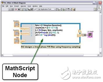
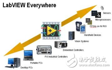
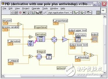
Overview The functional prototype system series is a series of articles to help you understand the prototype development process. Through reading, you can understand the key concepts, the advantages of prototype development, product selection discussions, and other technical resources. Algorithm Engineering Algorithm engineering is a term coined for applying algorithm design. It refers to the process of converting a draft algorithm on paper into a robust, fully tested, and easy-to-use implementation. Implementing algorithms to provide the required functions in a prototype system may be the most challenging part of the entire product development life cycle, but it may also be the most rewarding part. By applying real-world I/O, you can see the algorithm work with your own eyes. This article explains the problems developers may encounter in designing algorithms and the advantages of using graphical design to overcome these challenges. Algorithm engineering challenges the programming knowledge that only a few system-level designers can master. The programming knowledge required for programming for different platforms is usually precisely mastered by a few system-level designers. Basic algorithm implementation It takes time to implement the underlying algorithms for basic functions. Speed ​​is crucial in prototyping, and it is unacceptable for developers to fall into the dilemma of a known algorithm developed from scratch because of the lack of existing code. Repeated implementation of algorithms for multiple platforms With the development of functional prototypes, algorithms need to repeat functions many times in order to be transplanted to different types of systems. Code usually cannot work in different operating environments, which makes it difficult to extend the application from the prototype system to the deployment. Testing and verification Usually only at a later time can it be determined whether the system can really meet the functional requirements, and the cost of starting over is expensive. For example, the processor may not be able to execute multiple parallel tasks fast enough. It may not reach the required cycle time. It may also not be able to process processor-intensive analysis in real time. The advantages of graphical system design for algorithm engineering Graphical system design solves many potential problems in the algorithm engineering of the functional prototype system. Graphical system design is a way to solve design challenges by combining intuitive graphical programming with flexible commercial (COTS) hardware. You can use this method to use the same environment in all stages of the design. Now let’s take a closer look at how this method solves the challenges presented above. Multiple calculation models One of the advantages of graphical system design is that it allows programmers to create algorithms without considering the computational model (MoC) used for implementation. As the complexity of algorithms continues to increase, programmers must use different computing models to expand their code capabilities. Here are a few calculation models that you can use for graphical system design: data flow Data flow is a calculation model closely related to NI LabVIEW software. Using data flow requires the developer to enter all input data before starting execution. The data flow is an intuitive code structure, which makes the implementation of parallel processing and other applications very simple. Text math Text math is another tool for simply creating complex functions. Text-based mathematics is a method of implementing complex algorithms that can be written in a form that can be described in scripts and implemented in a form that can be read by humans. Examples of text math include formula nodes and LabVIEW MathScript real-time modules. With LabVIEW MathScript, you can choose the most effective syntax for algorithm development, whether you are developing algorithms, exploring signal processing concepts, or analyzing results. Figure 1: Reuse text-based code using the LabVIEW MathScript Real-Time Module C code Sometimes the code you use was originally created in C or C++. In this case, you don't have to abandon your past work. You can use the embedded C node or call library function node to directly call your previous code in LabVIEW. Use the embedded C node for the existing C code or write a small number or matrix algorithm, use the call library function node to access the C code in the DLL or shared library. Open software architecture In the past few years, the LabVIEW platform has been widely used in many design disciplines, so it is necessary to integrate data with different design and simulation tools. LabVIEW uses a variety of integrated tools, libraries, and file formats to achieve this interactive compatibility. LabVIEW also provides numerous standard integrations with other software tools and measurement resources, including: * DLLs, shared libraries * ActiveX, COM, and .NET (Microsoft) * DDE, TCP/IP, UDP, Ethernet, Bluetooth * CAN, DeviceNet, Modbus, OPC * USB, IEEE 1394, RS232/485, GPIB * Database (ADO, SQL, etc.) Using these tools, data integration from almost any measurement and control device is possible. By integrating LabVIEW with common standards for hardware communication, developers can ensure compatibility and scalability for many years to come. LabVIEW method Hundreds of functions in LabVIEW cover many traditional algorithms in mathematics, signal processing, probability, and control, and are the basis for constructing any customized algorithm. These functions reduce the burden of writing low-level code and provide engineers with time to focus on solutions rather than implementation details. Because the use of LabVIEW makes it very simple to collect real-world data, users believe that it is very valuable to be able to use actual data to test the algorithm, and thus to use repeated methods for fine-tuning. With this interactive testing method, you can experiment with different functions to check whether they give the expected results. For example, when using filters to process signals, you can choose from different solutions, collect the actual signal you need, and then view the results in a graph or file. If the result does not apply to the application, you can choose another filter. It is usually easier to collect actual signals and apply algorithms than to spend time in software simulation. Commercial hardware Commercial hardware stepping provides an easy way to quickly start prototyping, and uses graphical system design to help you implement local algorithms on many targets with integrated I/O. Use real-time processors in NI CompactRIO and PXI platforms to integrate I/O with deterministic control for more reliability. This is very important for hardware-in-the-loop applications, because the hardware and software need to be closely integrated to dynamically simulate the environment that the control algorithm manages to control. Processing Using a real-time processor with FPGA, you can integrate LabVIEW into your application and migrate code from one type of commercial hardware to another. For example, you can transplant the code that analyzes real-world I/O signals on a desktop computer, and you can use it on platforms such as PXI, PDA, and embedded processors without extensive rewriting. In fact, first designing and verifying the prototype on a desktop computer, and then converting it to a 32-bit processor, for embedded system deployment can greatly save the increased development time and repeated coding due to ignoring design constraints. Figure 2: LabVIEW target Tools for simulation and control design Since LabVIEW is an open platform, you can map your measurement data to simulation results. You can exchange simulation data for behavior modeling with real-time data. In addition, you can use simulated stimuli to drive physical measurements, providing a robust test environment. Use LabVIEW simulation to verify and estimate the performance of the design criteria. You can import the design into different simulation tools for early design evaluation. The next step includes automated layout or model building tools to automate the construction process. Save available system status information and output signals to help you debug applications and establish application performance specifications. Use the control block diagram in LabVIEW control design and simulation module to design linear, nonlinear, discrete or continuous control systems. Using this abstract programming style, you can program using traditional control concepts such as transfer function modules, integrators, differentiators, and feedback loops. Using advanced block diagrams, you can develop solutions at the conceptual level so that you can use past system experience and knowledge. Figure 3: PID control using control design and simulation Next step It is a challenging process to engineer the algorithm and realize the function of the prototype system. Graphical system design is a way to use the advantages of close integration between intuitive graphical software and commercial hardware to help you overcome challenges related to algorithm engineering, so that you can complete prototype system development faster at a lower cost. Main Marine Diesel Generator,Off Shore Diesel Generator,Platform Marine Generator,Marine Propulsion Engine Jiangsu Vantek Power Machinery Co., Ltd , https://www.vantekpower.com

