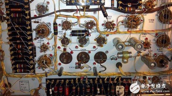
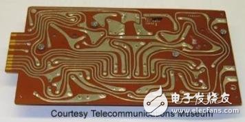
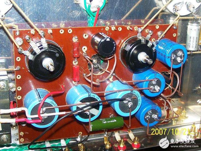
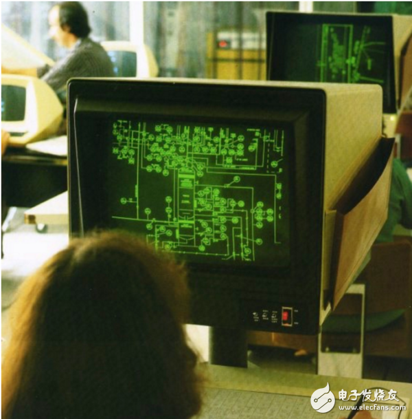
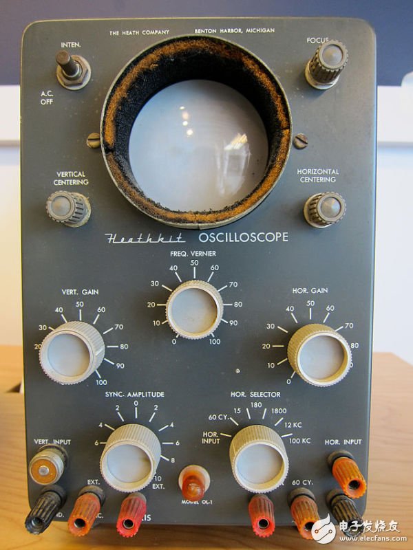
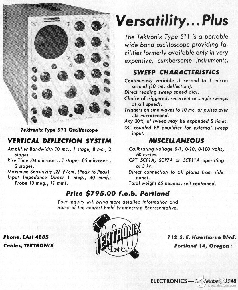
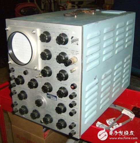
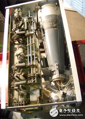
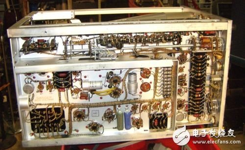
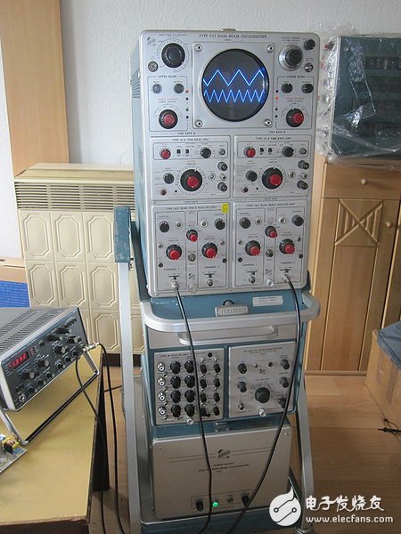
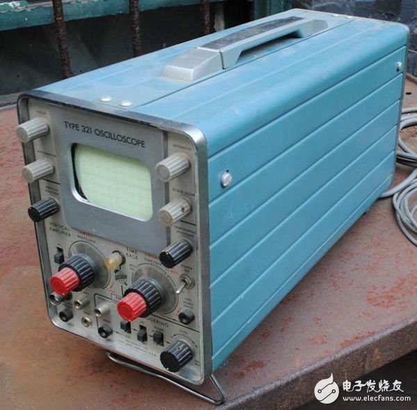
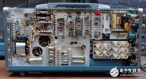
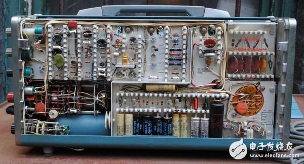
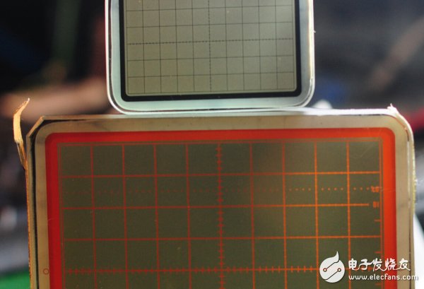
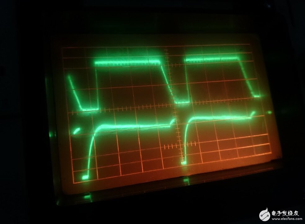
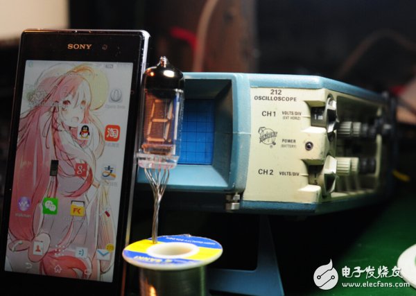
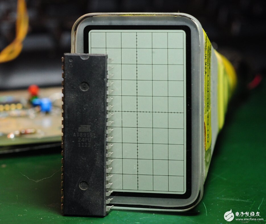
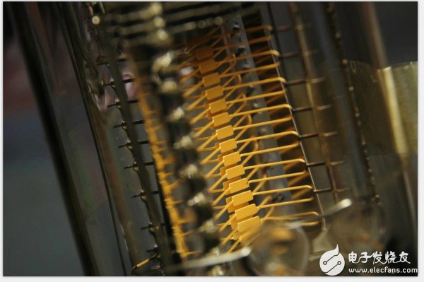
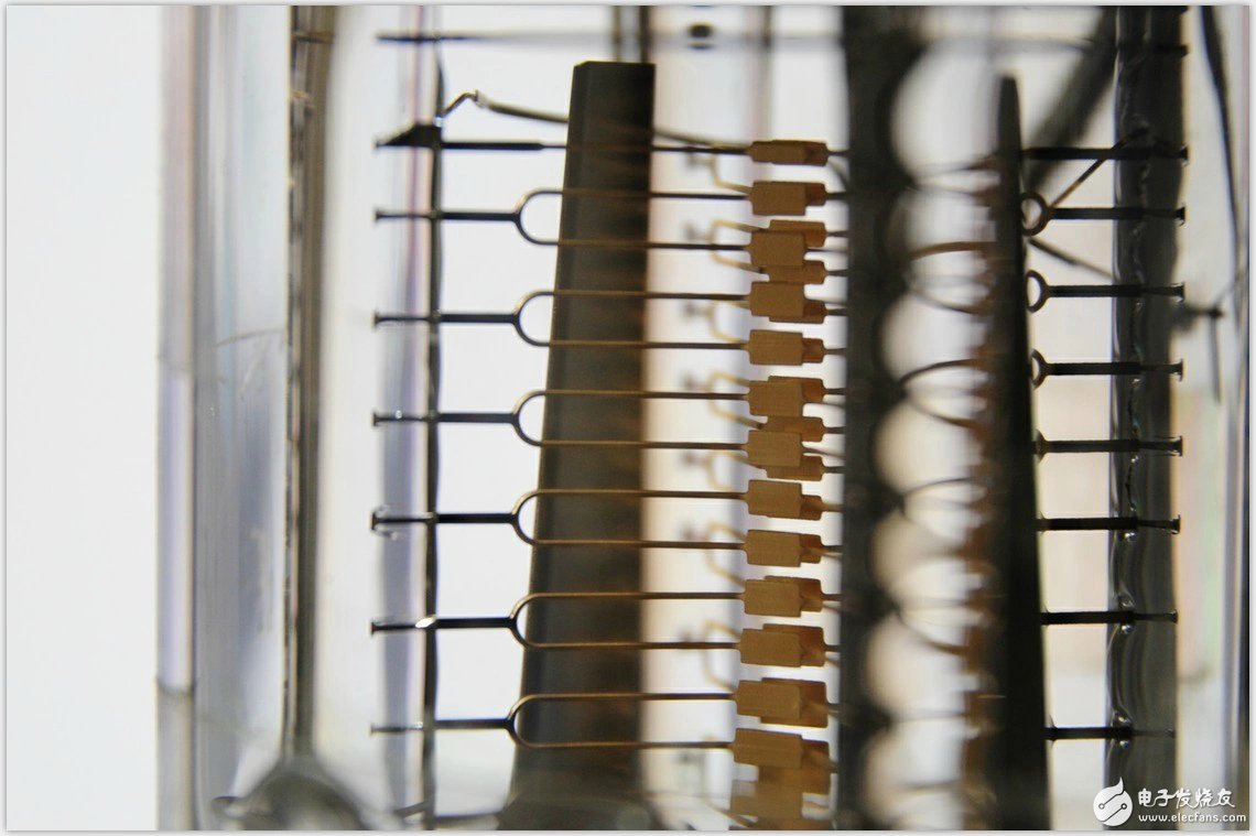
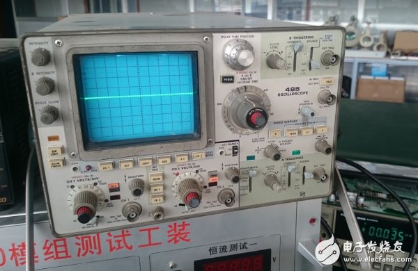
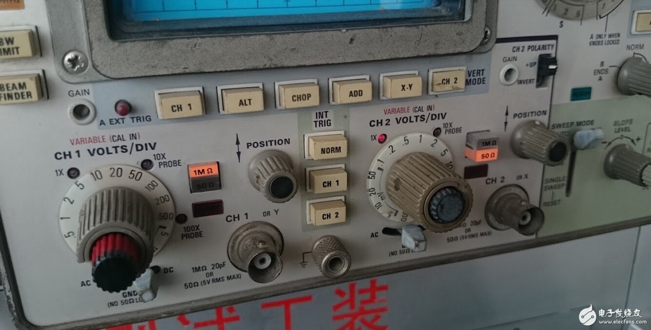
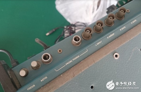
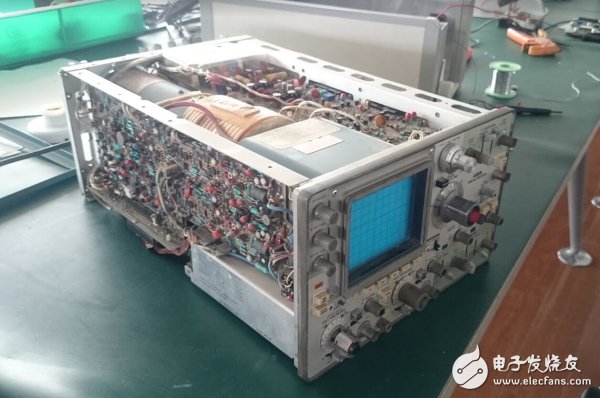
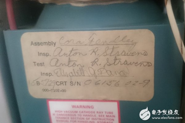
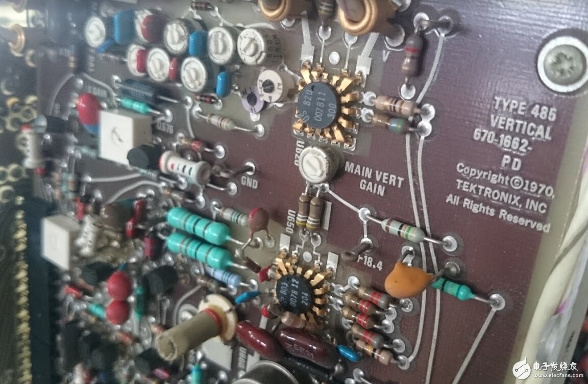
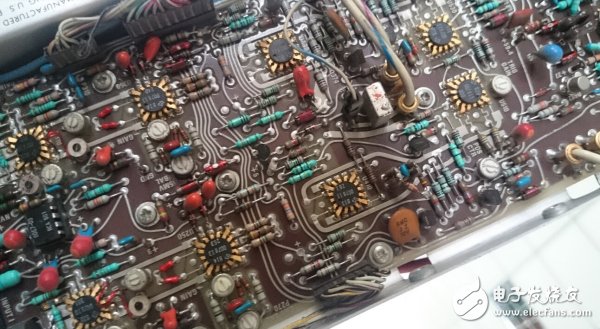
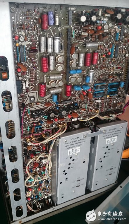
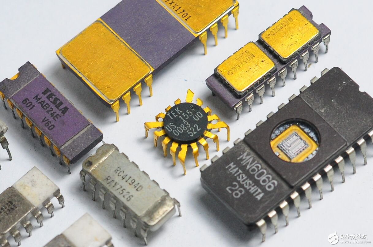
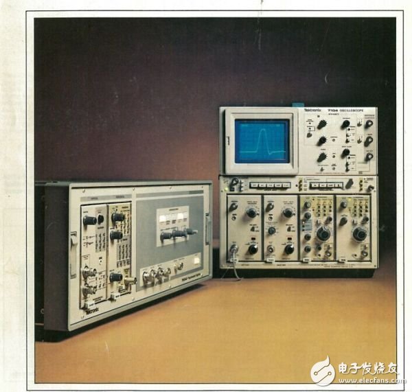
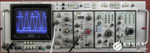
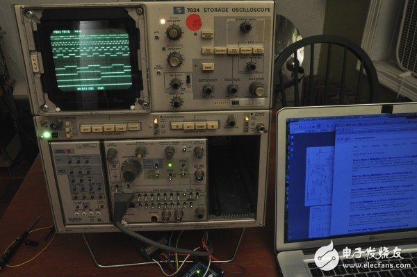
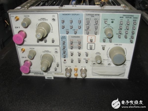
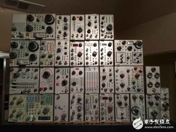
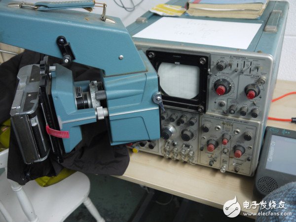
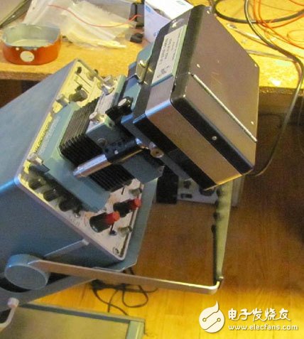
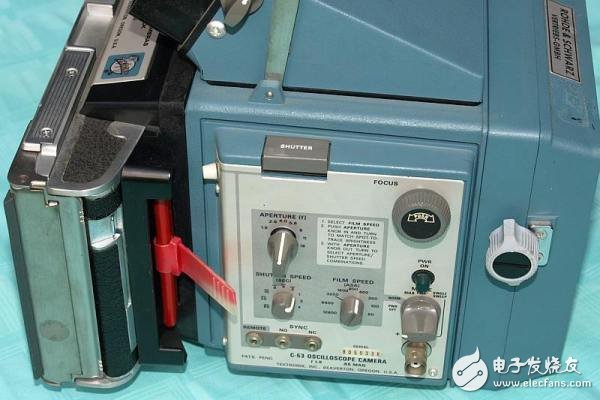
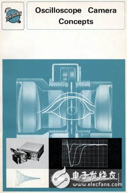
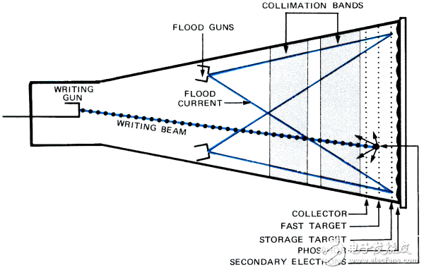
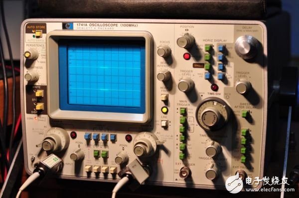
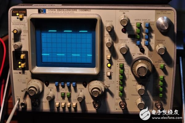
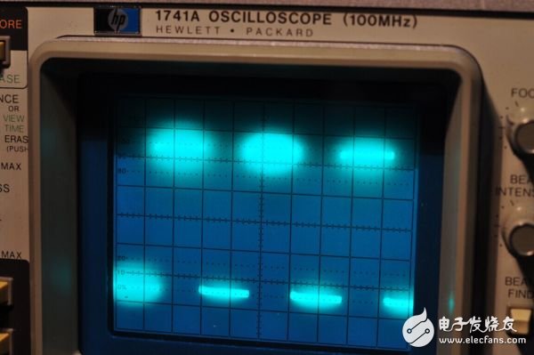
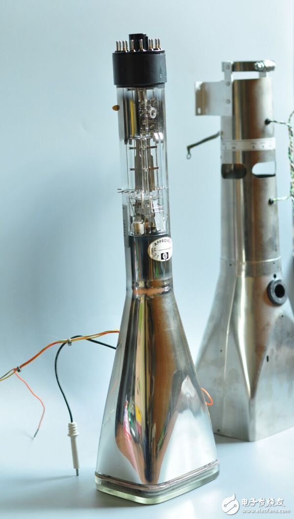
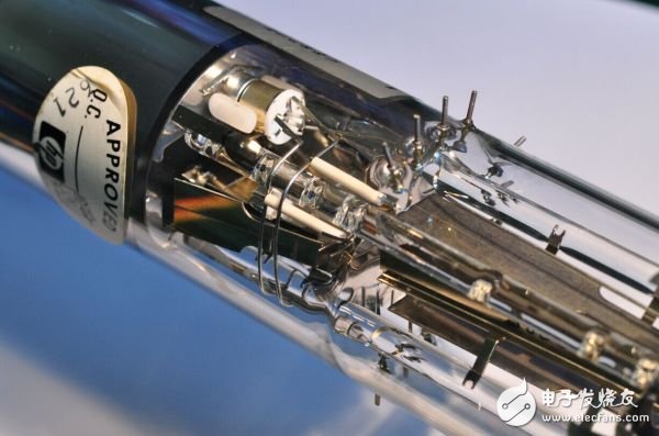
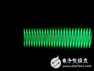
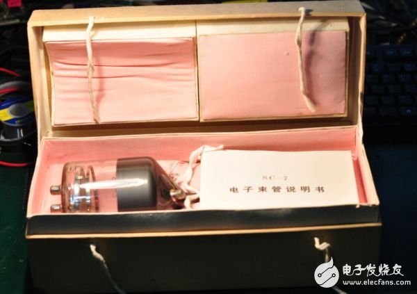
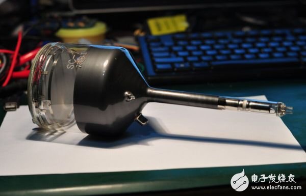
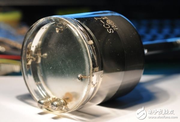
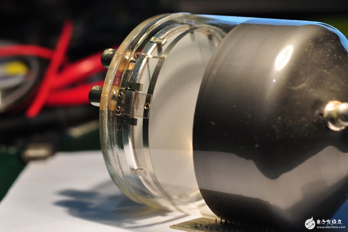
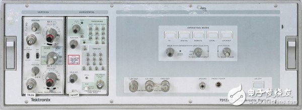
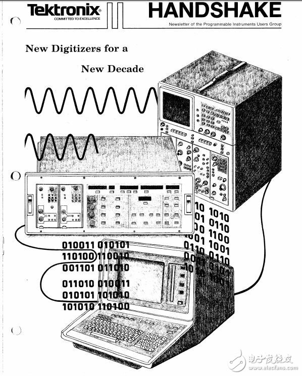
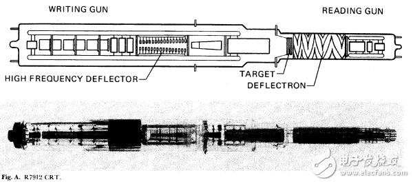
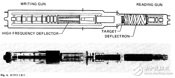
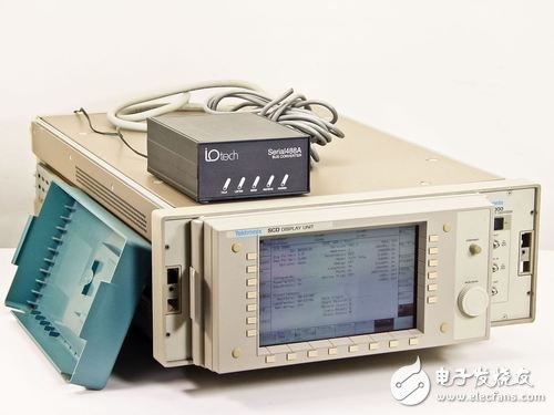
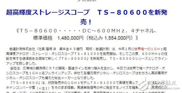
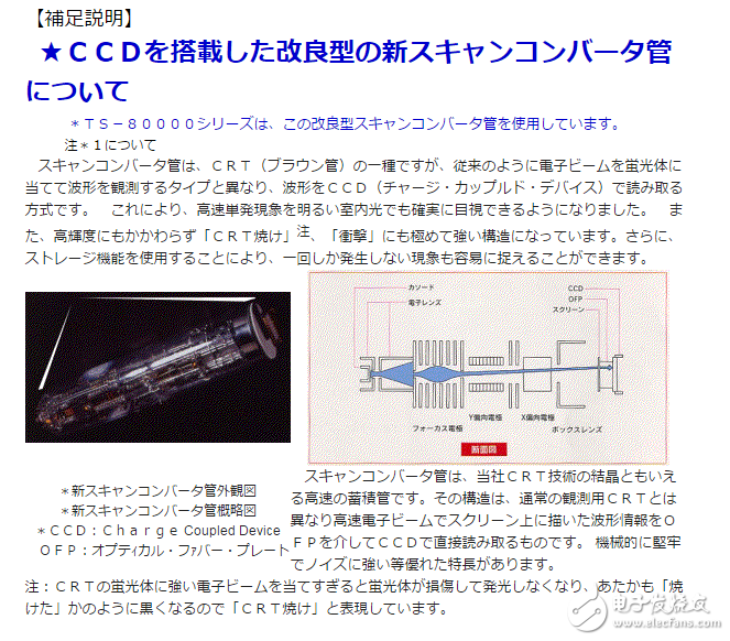
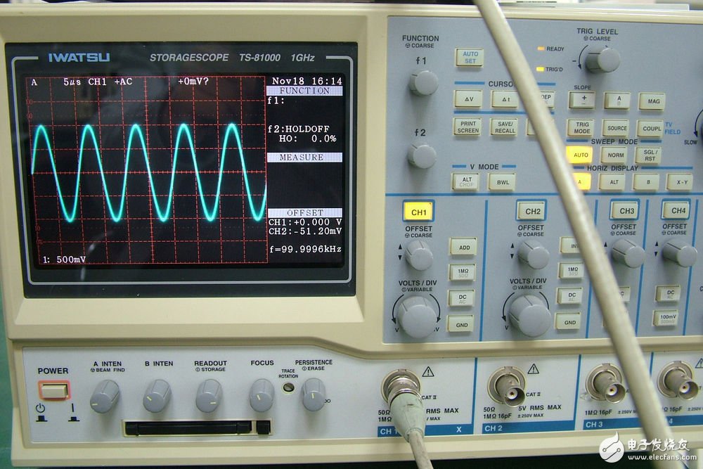
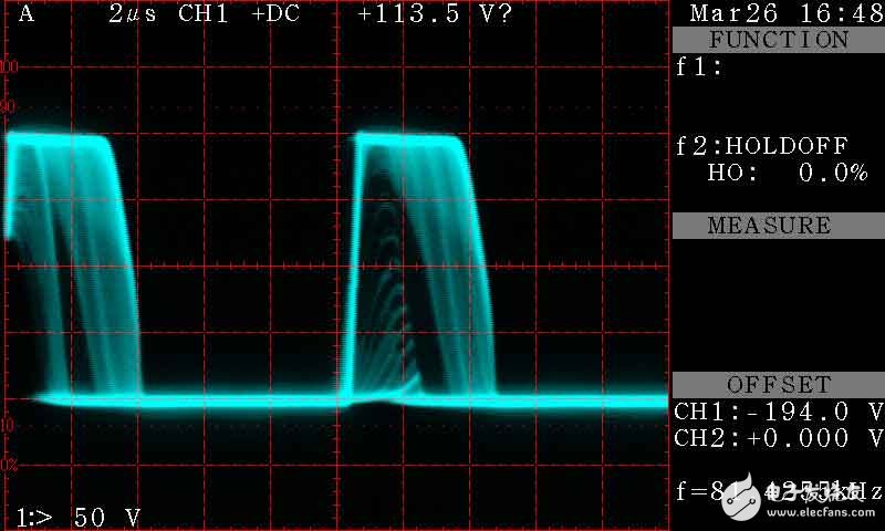
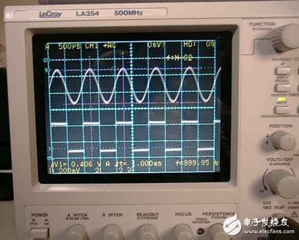
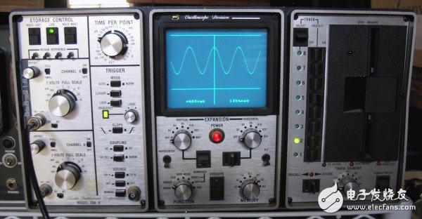
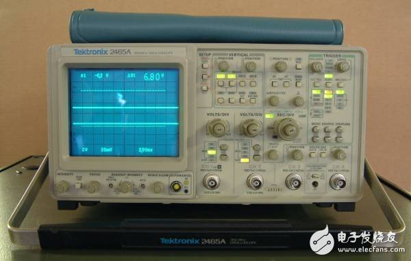
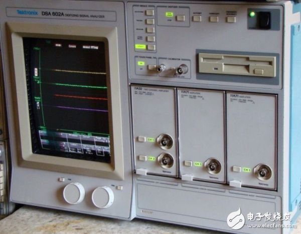
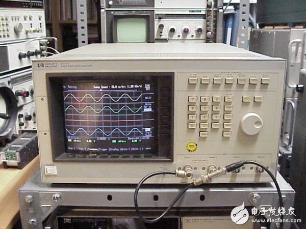
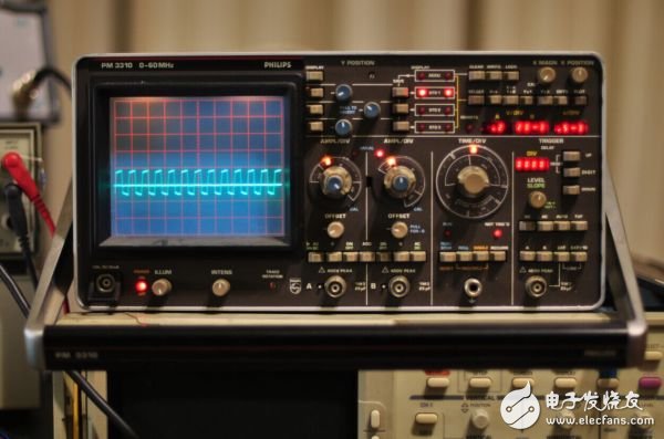
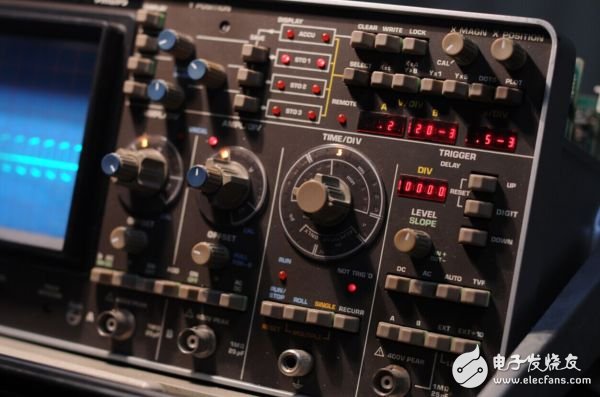
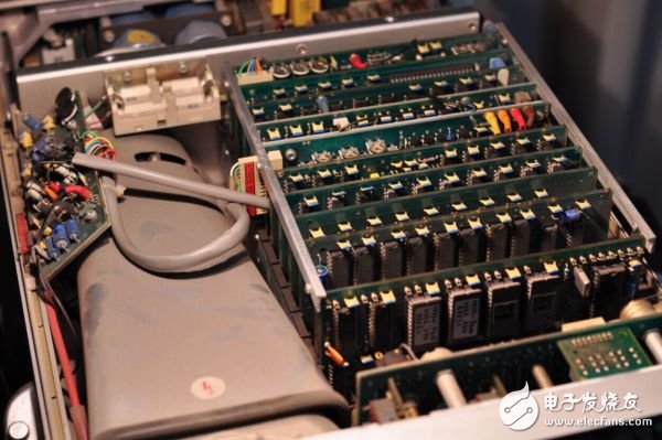
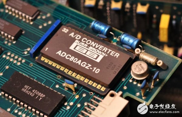
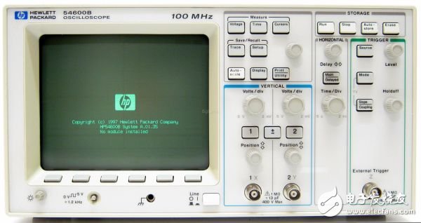
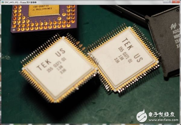
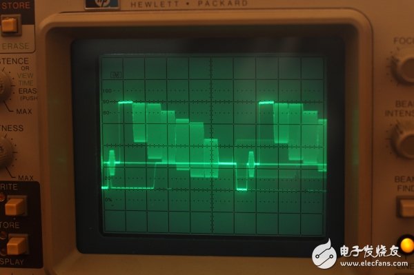
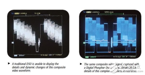
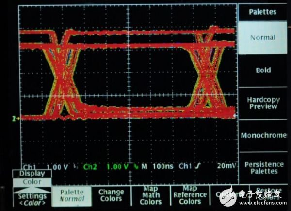
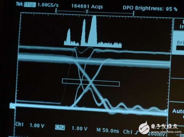
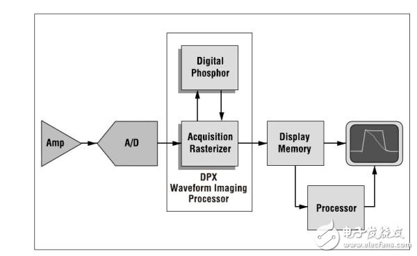
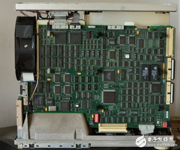
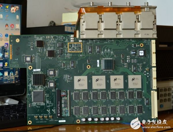
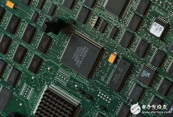
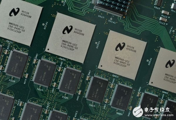
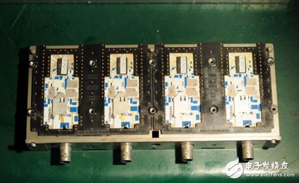
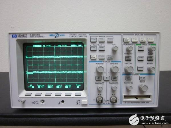
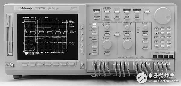
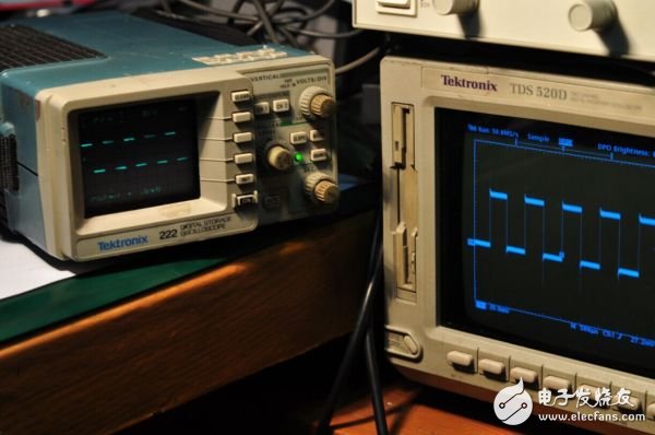
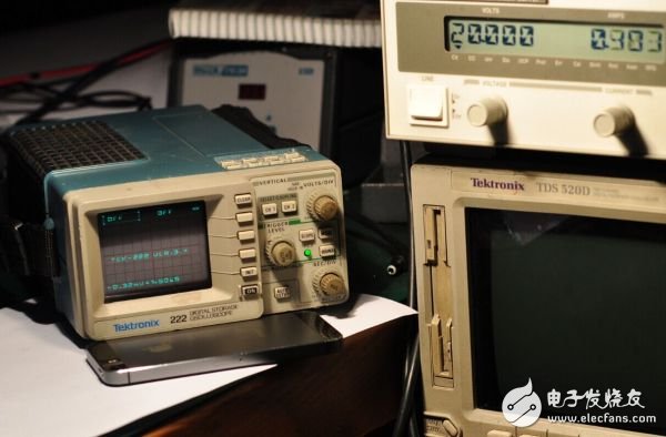
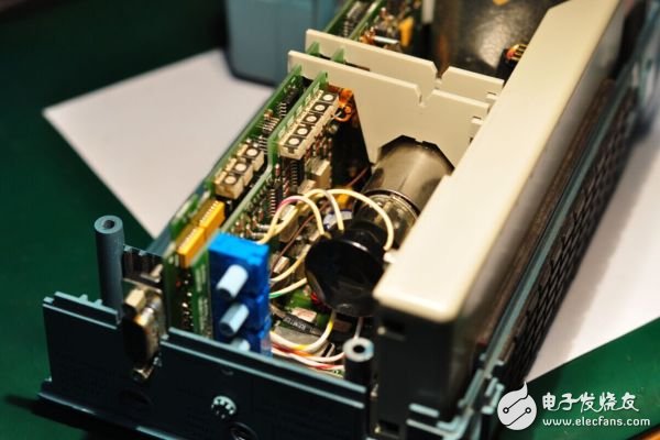
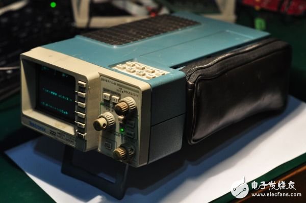
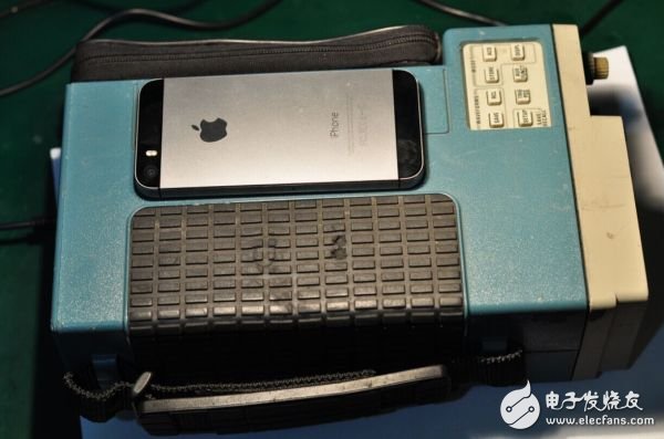
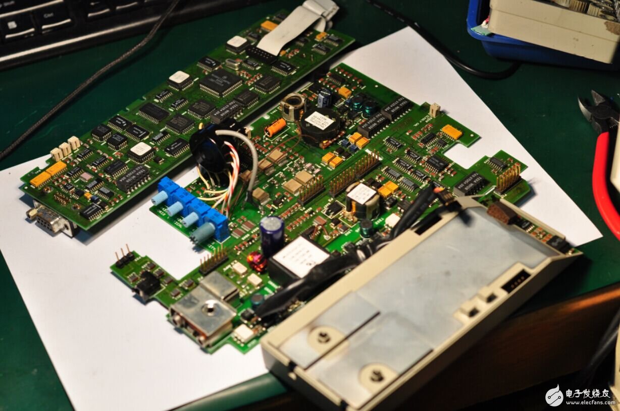
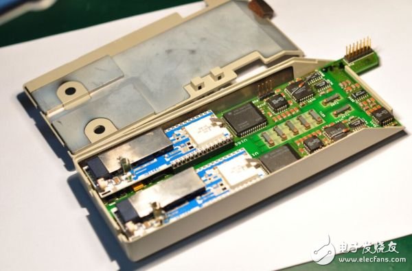
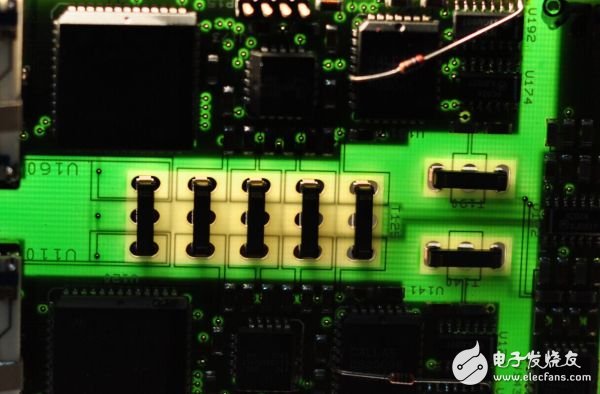
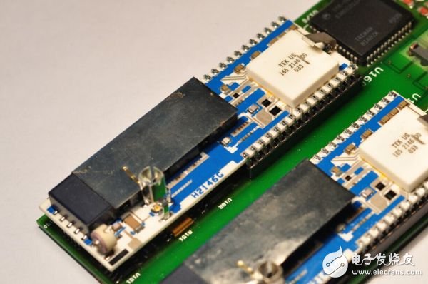
As the most basic comprehensive instrument in the electrical measurement industry, the oscilloscope is also involved in the design and manufacture of a wide range of fields, from semiconductors to specialty materials, from machining to electronic design. This requires a strong and complete industrial system as a support. But did the Soviet Union have all this in the early days? Why did the Soviet Union not do it? In fact, the market is also very critical. It depends on the strength of the state. It may be able to focus on solving problems in a short period of time and then invest in other problems. Some things cannot be continuously studied in depth. Only the continuous demand of the market continues to stimulate technological progress. Just like war, technology can make a huge leap. In addition, advances in some other technologies, such as electronic computers, have also been complemented by the development of instruments, which has also brought about a comprehensive improvement in thinking. Involved in the specific technology related to oscilloscopes, from the 1960s, generally speaking, the gap between China and foreign countries is not particularly large, because everyone uses electronic tubes, this thing has nothing to do with industrial machinery and equipment, mainly stamping and welding, etc. Etc. In addition, the special cathode coating material of the tube is also critical to the performance, but this is not out of reach. In addition, the oscilloscope bandwidth of this period usually does not exceed 40MHz. The difficulty is not particularly large. At this stage, we have not much difference with the technical reserve, mainly because the demand is not too much, resulting in some products falling behind in terms of process and structure. . Figure: Part of the TEK 511 oscilloscope, you can see that there are many text prompts printed on the backplane, which is more elaborate. By the way, the manufacturing process of this era, because the tube itself is large, and most of the devices with high voltage and high current, the size of the device used is very large, both domestic and foreign are installed components, that is, components are installed On the brackets, then connect them to each other with wires. This method is commonly known as scaffolding in China. In the mid-1960s, some semiconductor devices began to gradually replace the position of the tube, and the bandwidth of the oscilloscope began to reach 100MHz. At this time, the application of electronic computers began to gradually spread, which led to more demand for oscilloscopes. At this time (circa 1965), HP also released the HP-IB bus, which was later standardized in the 1970s as IEEE488, or GPIB. Through this control bus, the computer can control the operation of the electronic instrument, collect the data of the instrument and analyze it. This has brought us to a new level of use and understanding of data, and at the same time gave birth to the concept of automated measurement systems, which brought greater efficiency and better accuracy. At this time, there is still not much progress in China. High-bandwidth oscilloscopes place very high demands on processing technology and design, and electronic computers are not much in the country. As transistors shrink in size and power consumption, printed circuit board technology is beginning to be promoted, and electronic components can be quickly and orderly mounted through PCB boards while reducing parasitic parameters. Therefore, the manufacturing technology of the circuit board has also followed up development. Youtube This video was taken in 1969 by Tektronix about the entire process from PCB design to production. You can see how it was done at the time. It can be suggested that the elegant curves of the above picture are all drawn manually. The picture comes from an old predecessor DIY, but at that time the domestic PCB was basically like this. It looks a lot more rough. The main method is to punch and rivet the mounting points of each component, and then solder them to the rivets, and the opposite sides are connected to each other. Such a process is inefficient and the installation density is low. These auxiliary industries also seriously affect the integration of the instrument. In the 1970s, our catastrophe continued. The microwave semiconductor technology of the United States is advancing by leaps and bounds, and the microelectronic integrated circuit technology is changing with each passing day. The bandwidth of the conventional oscilloscope reaches 350MHz during this period, and the special oscilloscope can reach 1GHz. At the same time, the further development of semiconductor technology makes the oscilloscope fully programmable, and digital acquisition is also possible. For example, the analog oscilloscope of the same era already has a microprocessor, which can intuitively read the measurement parameters on the screen, and can transfer the parameters and waveforms to the computer. It was not until decades later that domestic analog oscilloscopes began to have this capability. At this time, our semiconductor industry has stopped and can only produce ordinary logic gate circuits. Of course, the CPU of the 8086 class is also copied, but think about it, 1 no one will use it, 2 cost is scary, 3 use these things to do measurement instruments, greatly increase the cost and complexity of the instrument, but not enough The computer is matched with it. At this time, the measurement demand mainly depends on the import (the Sino-US relationship is still okay). In this era, due to the needs of the instrument and the military, the United States began to make 4-layer boards and used early computers for EDA-assisted circuit design. such as. . . No, I don’t know how big the gap is. The 1980s was the era when PCs and bullies took off. In this era, thanks to the demand for ultra-large-scale circuits in many industries, oscilloscopes have followed the light and entered the digital age. Due to special requirements such as radar, GaAs semiconductor technology has grown rapidly and is used in RF measurement instruments such as network analyzers and spectrum analyzers. These other areas of technology have paved the way for high-performance digital oscilloscopes. However, due to the scarcity of related industries in China, there has been a huge technical fault at this time, and it has not been able to catch up until today. If you are interested, you can look at the various American bullies of the 80s, useful for a variety of CPUs, such as Z80, MC6800, MC68000, 6502, and so on. It has to be said that the market has played a huge role. Due to the manufacture of these consumer electronic products, there is also a huge demand for electrical measuring instruments. During this period, the extremely high density of components also promoted the maturity of SMD surface mount technology, which represents the integration of the circuit, stability, and production speed. In the early 1990s, with the increasing complexity of computers and various network systems, higher requirements were imposed on measuring instruments. At this time, the high-performance digital oscilloscope, which is mainly represented by the HP54600 series and the Tektronix TDS500 series, debuted. After a long period of technical accumulation, the digital oscilloscope at this time incorporates advanced semiconductor technologies such as microcomputers, DSPs, CPLDs, and specially designed ASICs and ADCs that represent core technologies, trigger controllers, and so on. In terms of software, it is also a collection of advanced measurement algorithms. It can be said that no matter which side, in that era, our gap is not a little bit. After all, the parts that make a 286 can't be completely localized. What about more advanced oscilloscopes? Therefore, the question of the subject is actually very broad in my opinion. He involves many fields. Although it may be from an instrument itself, it is mainly limited to several key devices. However, if you want to make these things, you will not get a few national technical breakthroughs to get the corresponding results. He is the product of long-term accumulation and progress, and also the crystallization of wisdom. At the same time, it is also an inevitable result of adapting to the development of the times and market demand. In the following, a more in-depth understanding of the concept of technology accumulation by a brief look at the history of the oscilloscope. Also, look at the brain holes of the seniors. Ancient times (before the 90s). HP has not been split yet, so he also produces electrical measuring instruments and is made up of instruments. After the split, the electrical and biochemical measurements are called agilent (now the electrical test is split again called keysight). The semiconductor technology is called avago. Similarly, Tektronix used MAXTEK to design and manufacture special custom parts for the company's instruments. Oscilloscope history | Wikiwand The starting point of an electronic oscilloscope is not easy to verify, so the prehistoric era is divided by the operating characteristics of the oscilloscope. The most common use we have today is the edge-triggered mode, which is often thought of as part of the basic functionality of an oscilloscope. In fact, before the TEK 511, the oscilloscope did not have the ability to trigger. In order to stabilize the display waveform, the oscilloscope at this time uses a technique called synchronous scanning. The oscilloscope scans freely at a fixed frequency to display the waveform. To stabilize the waveform, he also has simple comparator control to determine when to start scanning. However, due to the uncertainty of the scanning time, the time axis of the oscilloscope is also unstable. Such an oscilloscope cannot perform accurate time measurements or observe aperiodic signals. 00: The starting point for modern oscilloscopes: Tektronix 511 In 1947, Tektronix released his first product: the 511 oscilloscope. The biggest difference with his predecessors is that he has the precise triggering system for the first time, which is actually the edge level trigger that every oscilloscope we can see today. When the input waveform meets the polarity and threshold set by the trigger comparator, the oscilloscope begins a scan at the time set by the time base knob. In this way, the starting level of each scan on the waveform can be determined by adjusting the trigger level, and the time of each scan is known. The accurate time domain analysis of the measured signal can be performed by the grid on the screen. This is a huge leap, and the simple principle has become a necessary function for every oscilloscope today. I have to say that he is the starting point of modern oscilloscopes. In the 1960s, when RF semiconductor technology advanced rapidly, companies such as HP and TEK urgently needed high-performance solid-state amplifiers and replacement devices for various tubes. Since general-purpose devices companies could not provide these components, they set up their own R&D departments to meet domestic demand. . Since the military also has huge demand, the most important funds are naturally not a problem. In the case of an oscilloscope, to make the bandwidth higher, an oscilloscope with higher brightness, more precise focus, and faster slew rate is required, as well as a high-speed preamplifier/Y-axis amplifier. Since the 1960s, other tubes besides the oscilloscope have been replaced by transistors and integrated circuits. The Tektronix 555 oscilloscope, which began to appear in late 1959, has a bandwidth of 30MHz and is fabricated using a complete tube structure. The power consumption and volume are huge. The bottom layer of the trolley is his power box. . . . . Obviously such an oscilloscope is so huge that it is simply impossible to leave his car. In the early 1960s, as the mass production of transistors was gradually solved, the process of solid state of the instrument began. At this time, Tektronix introduced the Model 321 oscilloscope. He used almost all of the transistors, and some of the tubes in the early models worked in high-voltage areas, and later models replaced them with new transistors. The oscilloscope at this stage is reduced and the weight is reduced. It can finally be taken off the cart, placed on the table, or easily moved to some special measurement site. Huge market demand spurred them to develop all the accessories they needed, and led to other industrial projects, such as precision machining equipment for glass and metal stamping equipment. In the late 1960s, the United States was able to manufacture precision internal oscilloscopes. That is, the grid on the screen of the oscillating tube is engraved on the glass surface inside the oscillating tube. This makes the reading error smaller. In the same era, domestic oscilloscopes were all engraved on the acrylic sheet and placed on the front of the screen. There were different errors from different angles. In addition to the lack of actual demand, it was not until the late 1980s that a small portion of the inner oscilloscope was produced, mainly for ultrasonic flaw detectors. The two oscilloscope tubes I have are from the TEK 212 and 2430 oscilloscopes. The two tubes are about 70-80s. They have detailed inner scribe lines, which can be clearly seen when there is light (on the oscilloscope). There is a tungsten light bulb backlight). Still in my office, a 80M domestic 20M oscilloscope, he is acrylic engraved, 1cm from the oscilloscope screen, which brings a very large reading error, and even if there is a light, the line is also Not easy to see. A very small TEK 212 handheld analog oscilloscope, about the product of the early 1980s, mainly supplies military demand. The bandwidth is 0.5MHz. The TEK 2430's sophisticated and beautiful accelerating electrodes in the oscilloscope tube allow the electron beam to carry a relatively high amount of energy, so that the oscilloscope can still have sufficient brightness for observation at high sweep speeds. Ok, it’s a bit far. Come back When the integrated circuit enters the oscilloscope, I did turn a lot of information and it is difficult to determine. However, our company once had a Tektronix 485 left by the old predecessor. He was born in 1972. The company was produced around 1978. His bandwidth is 350MHz, which was a realm of domestic goods at that time. And the interior is very complicated and the manufacturing process is quite sophisticated. Unfortunately, one day when I was playing with him, suddenly it was black and the fan stopped spinning. Suspected that there is a problem with the switching power supply (yes, in 1972, the switching power supply was used). Then the site was dismantled for maintenance, and it was too complicated to find it. The whole machine is wrapped in PCB inside and outside, and the power is at the center. . . So I took some pictures and put them back. Return to the warehouse to sleep. Ok, no more nonsense, above: Still able to boot photos Beautiful panel, with some buttons for backlighting or tungsten bulbs. At the rear of the machine port, it can be seen that there have been active probes during this period: he has two active probe power supply interfaces. Remove the screws on the back and pull out the case. All the densely packed boards Product inspection signature on the oscilloscope. The unique integrated circuit that TEK customized at the time. There are a lot of them. . . The input channel section is also very complicated. The individual ICs that I received in my spare time, the strange one in the middle is TEK's own custom products. These things are very good for our technical staff at the time, and it is difficult to guess his specific use. The further emergence of integrated circuits and microprocessors has opened up a good way for the automation of oscilloscopes. As the boss of Tektronix, naturally, this opportunity will not be missed. In the mid-1970s, all aspects were met and the time was ripe. Tektronix introduced the 7000 Series Modular Oscilloscope. Another host display unit is equipped with various modules to define various functions of the instrument. And it has a variety of modules. . . You can see it here, it is too much. For example, the horizontal and vertical modules required by the oscilloscope, the TDR module that crosses the frequency domain and the time domain, the frequency meter required for the radio frequency, and the spectrum analyzer module. The logic analyzer module required for digital circuit verification at the time. . . . Of course, no matter how he changed his magic, he still simulated the oscilloscope. Analog oscilloscopes have many inconveniences, such as low bandwidth and inability to store. In the 1970s, when high-speed digital-to-analog converters were not developed, high-energy physics experiments and microwave and radar system measurements required high-bandwidth, analog oscilloscopes that could be stored. So there are some real black technology products (absolutely different from those of a certain rice promotion). Let's talk about bandwidth, the conventional analog oscilloscope, that is, the kind of screen that looks at the screen with the human eye. The highest record holder is the product of Japan Iwasaki (should also be the end of the 80s) (the model I really don't remember), his bandwidth is up to 470MHz! In the 1980s, Tektronix products could only reach 400MHz (2467B). Since the oscilloscope tube of the ordinary desktop oscilloscope has a large display area, the electron beam stroke is long, and the Y-axis driving capability cannot be increased in an unlimited manner, thereby limiting the overall bandwidth of the oscilloscope, so that the bandwidth of some oscilloscope tubes can reach 600 MHz. But the driver circuit is difficult to achieve such a level. Let's talk about storage. Everyone knows: If an analog oscilloscope uses a single trigger, the waveform sweeps through the screen, and after a few ms of afterglow, it will disappear forever. So technology has two directions, one is an oscilloscope camera. This dedicated camera is mounted on the oscilloscope screen and keeps the shutter open all the time. After the oscilloscope triggers, the shutter is closed and an exposure is completed. This is a clever approach, but every time you want to see the recorded waveform you need to rinse the film. Two oscilloscopes with dedicated cameras that look a bit strange Some adjustment options on the side of the C-53 camera, such as focus, aperture, shutter speed, film speed, etc. TEK's 1973 booklet on the use of oscilloscope cameras. Due to the cumbersome use of the oscilloscope camera, there is another technology, namely the memory oscilloscope. This oscilloscope has a special storage grid mounted behind the screen and a dedicated readout gun inside the oscilloscope. After the main electron gun completes a scan, an electronic gap is left on the gate. Then, the read-out electron gun is turned on, and the electron-emitting screen is uniformly emitted to the storage gate. One part is blocked by the storage gate, and the other part is irradiated onto the screen through the gate, and the stored waveform is reproduced. A schematic diagram of the structure of the oscilloscope is stored, and it can be seen that he has two more FLOOD GUNS and a set of gates placed behind the screen. However, this oscilloscope can only be stored for a few minutes and then blurred due to electronic leakage. The representative model of the later stage is HP Model 1741A. This special tube is also used in radar displays and RAM memory in early computers. This kind of oscilloscope tube requires more precise mechanical structure, and the tube with low bandwidth can be successfully produced in China. My 1741A oscilloscope At this point, the oscilloscope is not connected to the probe, and the waveform just stored is displayed on the screen. After a few minutes, the waveform begins to blur and eventually turns into a green screen. The 1741A oscilloscope tube, at this angle, can be seen with a readout electron gun with a white ceramic back cover. This shows the low-speed scanning process in the storage mode, first full-screen green light, which is the "erase" of the oscilloscope, followed by a scan, the waveform still does not disappear after the first scan. In China, the SC-7 storage tube produced in 1973, he replaced the phosphor with an electronic target for recording and reading data. By the mid-1970s, computers were also miniaturized, and they were used more in the field of measurement control and analysis. This requires an electronic instrument to record his measurements and digitize them. This seems to be a problem for oscilloscopes because it was not possible to produce high-bandwidth, high-sampling ADCs at the time. At this time, the United States has mobilized its brains. This time, Tektronix developed the Model 7912 (circa 1973) digitizer (DigiTIzer). 7912AD digitizer The advertising brochure for this type of device focuses on his ability to connect to a computer. He still uses an analog oscilloscope with a bandwidth of up to 1 GHz, which is about 2 Gsa if it is equivalent to the sampling rate of a digital oscilloscope. It also provides a digital waveform output of approximately 12-bit dynamic range. How did he do it? Tektronix uses the Scan conversa TIon tube. This is a wonderful oscilloscope tube. He has two heads, one is an oscilloscope, which is responsible for waveform scanning, and the other is a camera tube for image recording (the product before CCD has not been used in large quantities). The center of the two tubes is the recording target. The oscilloscope emits a scanning electron beam to the recording target, and then is output by the camera tube and the low-speed AD converter to complete recording of the high-speed signal. The SC108 scan conversion tube used by the 7912 digitizer. This long thing can be called a brush screen artifact ~ This is equivalent to an analog FIFO. Solving the technical problems of the time, this tube has been used by Tektronix in the late 1980s to produce the SCD5000 series of digitizers. The SCD5000 digitizer, this time he has an optional LCD screen for viewing the recorded waveforms. Later, the same technology as the SCD5000 was introduced by the Iwasaki Corporation of Japan in the year of 2001. However, the camera tube was replaced with a CCD. LeCroy LA354 is also something like this. It is actually an Iwasaki brand. At this time, Tektronix' digital oscilloscope has already crossed the 10Gsa sampling rate and reached 20Gsa (TDS7404/7254). The promotional instructions of the TS-80000 series briefly show the structure of the scan transducer. In fact, the CCD is a wave tube, but the oscilloscope has a small target surface and is easier to achieve high bandwidth. TS-80000 with his screenshots. This liquid crystal oscilloscope uses such a smart way to achieve the effect of an analog oscilloscope, and can store and measure. LA354 is actually a Japanese OEM. In addition to digitizers, there were some well-structured digital oscilloscopes in the 1970s and 1980s. The pioneer of digital oscilloscopes is said to be the British company Nicolet, who built the first digital oscilloscope and used tape to store data. However, this information is not very clear, and I did not find the picture of the first digital oscilloscope. The digital oscilloscope above was the product of Nicolet in the early 1980s. Very fashionable to use an 8-inch floppy drive to store waveforms. After the chaos of the 1970s, it is possible that these vendors have found that the starting point for modular devices is good, but they are not perfect. So after a long period of accumulation, the oscilloscope began to appear in various special subdivision purposes to meet different measurement needs. For Tektronix, the general purpose oscilloscope series is mainly the 2400 series. Most of them are analog oscilloscopes, but with the addition of a new AUTO function, the oscilloscope has some simple detection circuits to test the frequency of the input signal and Vpp. In this way, simply input the measured signal to the oscilloscope and press the AUTO button, the oscilloscope will automatically analyze and convert to the optimal range. This provides great convenience for user operations. For the analysis of high-speed digital signals, Tektronix introduced the DSA digital signal analyzer. In fact, this is the predecessor of the sampling oscilloscope used today. His input channels are designed to be replaceable and can be replaced with input sampling heads or TDR heads. Bandwidth up to tens of GHz In addition to producing analog storage oscilloscopes, HP's digital oscilloscopes are primarily targeted at automated measurement systems. The instrument is completely controlled by the GPIB bus, so it must be said that the front panel design is not very practical. I just said that the Tektronix 2400 series is mostly analog, but there are also a few ones: let's talk about other analog FIFO storage oscilloscopes. In the 1980s, high-frequency semiconductor technology was very mature, so there was a use of CCD to store waveforms. The oscilloscope (what is the camera CCD, he was originally developed as a data storage, and the sensitization is just an attached function). This type of oscilloscope represents the model Philips PM3310/3311, Tektronix 2430/2431. The sampling rate can reach 200MHz. The CCD component is like a serial shift register of analog signals. The analog waveform is quickly shifted in by the high-speed sampling clock and then moved out to the ADC for digitization driven by the low-speed read clock. It is also a more witty approach, and the cost is much lower than the scan converter. My PM3310 oscilloscope, the last picture is his low-speed ADC, which is about 12KHz. With the CCD memory, the sampling rate can reach 60M. However, I have repeatedly checked the maintenance manual and still can't determine which part of the CCD, or which IC. In the late 1980s, Tektronix and HP discontinued production of analog oscilloscopes and devoted themselves to digital oscilloscopes. Among them, HP first introduced the 54500 series, and the sampling rate is not too high, a few hundred M range. However, for many applications, the recording requirements can be met. With the practical use of high sampling rate ADCs in the early 1990s, Tektronix has also introduced a very classic TDS500 series oscilloscope and defines the basic architecture of digital oscilloscopes in the coming decades. In order to compete with Tektronix, HP introduced the 54600 series with panel operation similar to a general purpose oscilloscope. I opened the first generation of the TDS500 series ADC, which was produced in the early 1990s until around 1994. There are two cores, one is sample/hold and the other is a pipe-line ADC. For example, the TDS540 has a bandwidth of 500 HMz and a real-time sampling rate of 1 GHz. This means that the digital oscilloscope is really practical and has good adaptability, and it can replace the analog oscilloscope in many occasions! However, these early high-performance digital oscilloscopes also faced the problem of too low waveform update rate, dozens to hundreds of times per second, and could not display rich waveform information like an analog oscilloscope, and could not have the afterglow effect that an analog oscilloscope can exhibit. (If you have seen CVBS video signals with a low-end oscilloscope, you should feel more). Observing a video signal with an analog oscilloscope has a delicate brightness change due to the difference in the scanning speed of the signal itself. The synchronization period of the video signal is 50 or 60 Hz, and the wide block area is the color scan signal, and its frequency is much higher than the sync signal period, while the analog oscilloscope's Y-axis bandwidth is constant, independent of the scanning speed, so it can be fine Show these waveforms. Ordinary digital oscilloscopes generally use a lower sampling rate over a longer time base. This causes aliasing in densely populated areas, and finally only some erroneous low-frequency aliased waveforms are acquired. The left side is the effect of a general digital oscilloscope to observe the video signal. Lost a lot of detail, the right side is a digital phosphor oscilloscope, he is very close to the effect of an analog oscilloscope, which is discussed later. The current low-end domestic oscilloscope is still the same, the superimposed hierarchical information of the waveform can not be obtained from the screen, and the oscillating waveform of the switching power supply with a spike is measured, and the oscilloscope cannot record the details. Fine glitch pulses are often not seen. This is because the traditional oscilloscope stops collecting after each trigger, and then the CPU starts to read out the sample memory and update it to the video memory, which delays a lot of time. The oscilloscope may miss a large number of critical waveforms during data processing. In response to these problems, Tektronix has introduced the TDS500B/700A oscilloscope with instaVu technology since 1996. His approach is simple and violent. Compared to the sampling rate used by the previous digital oscilloscope timebase, the instaVu oscilloscope uses a higher sampling rate to continuously acquire waveforms, avoid aliasing, and superimpose it in RAM, then every 30ms. Update the screen once, so that a large number of superimposed waveforms can carry more sporadic information and further approach the effect of the analog oscilloscope. In 1997, the improved instaVu oscilloscope was released: TDS500C/700C, which can capture up to 400,000 waveforms per second compared to the previous generation! Analog oscilloscopes are limited by retrace time and can be equivalent to approximately 200,000 waveforms per second. instaVu oscilloscope: He can display a large amount of superimposed waveform information, but can not provide three-dimensional data of the waveform. At this point, the digital oscilloscope has only the last difficulty, that is, the afterglow information that the analog oscilloscope can provide. The afterglow can tell us the frequency and speed of the waveform. For example, the analog oscilloscope does not easily see the fast and steep rising edge of the square wave because the electron beam There is not much time left on the edge to fully excite the phosphor. Tektronix made further efforts to release the epoch-making TDS500D/700D series of digital phosphor oscilloscopes (Digital Phosphor Oscilloscope) in 1998. He is a further improvement of instaVu. Based on the more powerful DPX fluorescence processor, the overlap ratio of each waveform is calculated while superimposing the waveform. Therefore, the digital oscilloscope has the Z axis other than the X and Y axes for the first time. The brightness axis, at this time, the digital oscilloscope can also observe from a three-dimensional angle. It is also the waveform of the above figure, which is presented on the DPO oscilloscope, and the probability of occurrence of the signal is presented in different luminances. The block diagram in the DPO brochure, he has parallel data processing capabilities, waveform acquisition and update, CPU and DSP can also continuously calculate parameters to refresh to the screen. The DPX fluorescence processor is part of the independent work. TDS784D oscilloscope 1G bandwidth, 4Gsa sampling rate. This is the last batch of products. It was shipped in 2001. He replaced the newly developed ADC and DPX controllers. These components were later used in the TDS5000 and 7000 series oscilloscopes. Motherboard Acquisition board CPU and an ASIC. His CPU is MOTOROLA MC68040, operating system VxWorks The DPX controller on the acquisition board and a large number of sample buffers. It can be seen that the craft is still very complicated, and the domestic cottage still has some pressure (in fact, 41 can't do this 6). But for private enterprises, they need to invest huge costs. Obviously there is no need for this. After all, investment may not be rewarded. @MIKA also mentioned the problem of analog input This is the front-end channel of the TDS500D Series oscilloscopes. Because this generation of front-end power consumption is very large, it is done on ceramic circuit boards. And he can see that he used the advanced laser adjustment technology at the time to ensure the final channel consistency and stability. I have also been exposed to the oscilloscope boards of HANTEK and RIGOL. There are basically no adjustable capacitors there, and I need to adjust them when I am calibrating the instrument. The first generation of DPO oscilloscopes has only 16 levels of luminance, and the almost unlimited brightness level of analog oscilloscopes seems to be completely useless. In fact, he is already very good, relying on the flexible measurement capabilities of digital oscilloscopes and powerful analytical performance, it is finally completely Replaced the analog oscilloscope. a signal in jitter Test square waves, the edges look like the effects of an analog oscilloscope There seems to be a phenomenon of metastable state. åŒå¹´ï¼Œæ³°å…‹TDS694Cæ•°å—示波器的带宽到达3GHzï¼Œå®žæ—¶é‡‡æ ·çŽ‡çªç ´10Gsa大关。 . .进入新世纪,除了日本人还çŸæœŸå†…æ£é¼“了一下扫æå˜æ¢ç®¡ï¼Œæ³°å…‹ï¼Œhp(æ¤æ—¶å·²ç»æ˜¯agilent)以åŠLeCroyå…¨é¢çš„把高端示波器转å‘X86å¹³å°ï¼Œä¹Ÿå°±æ˜¯å°†ä»¥å‰ç¤ºæ³¢å™¨å†…惯用的MC68000系列或者ColdFire CPU转æ¢åˆ°PCå¹³å°ï¼ŒåŒæ—¶å…·æœ‰è¾…助DSPæ¥å®Œæˆæ³¢å½¢åˆ†æžï¼Œä½¿å¾—示波器的测é‡èƒ½åŠ›ä»¥åŠæµ‹é‡é€Ÿåº¦è¿›ä¸€æ¥æ高。 我现在业余使用的TDS7054示波器。他是TEK在01年推出的,用æ¥æŽ¥æ›¿TDS700D系列的pc-based示波器。拥有更好的è§å…‰æ€§èƒ½ï¼Œæ›´å¿«çš„速度,更强大的分æžèƒ½åŠ›å’Œæ›´åŠ çµæ´»çš„通讯端å£ã€‚ 以上是90年代泰克示波器的主è¦å‘展路线,ä¸è¿‡è¿™å¹¶ä¸æ˜¯90年代的全部。在90年代示波器领域出现了一些新的概念,在当时å—é™äºŽå¤šç§æŠ€æœ¯é™åˆ¶å¹¶æœªèƒ½å¸¦æ¥å¾ˆå¥½çš„实用效果。ä¸è¿‡åœ¨è¿‘期这些技术é‡æ–°æŠ•å…¥å¸‚场,使得示波器的观测能力进一æ¥æ‰©å±•ã€‚ 比如:混åˆä¿¡å·ç¤ºæ³¢å™¨ æ··åˆä¿¡å·ç¤ºæ³¢å™¨çš„概念最早由HPå…¬å¸æ出。主实现方å¼æ˜¯å°†ç¤ºæ³¢å™¨ä¸Žé€»è¾‘分æžä»ªä¸€ä½“化生产,逻辑图与波形图åŒæ—¶æ˜¾ç¤ºï¼Œç›¸äº’å‚考。在数模结åˆç³»ç»Ÿæˆ–者数å—系统的物ç†å±‚验è¯ä¸å‘挥了很大的作用。 这应该是第一å°MSO,带有16个逻辑(数å—)通é“。åŒæ—¶è¿™å°æœºå开始使用最新推出的MEGA ZOOMé‡‡æ ·æŠ€æœ¯ï¼Œæ˜¯DPO的竞争技术,也能带æ¥æ¨¡æ‹Ÿç¤ºæ³¢å™¨ä¸€æ ·çš„余辉效果。那么?在MSO之å‰å‘¢ï¼Ÿ 在HP推出MSO之å‰ï¼Œæˆ‘ä»¬è¿˜æœ‰è¿™æ ·ä¸€æ¬¾ç«æ˜Ÿçº§äº§å“——TLS216.它是一å°æœ‰16个模拟通é“的示波器。 . .泰克管它å«åšLogicScope。具体应该是92å¹´å‘布TDS500系列架构å–å¾—æˆåŠŸä»¥åŽï¼Œåˆ©ç”¨TDS500的框架设计出æ¥çš„怪物。他有2Gsaçš„é‡‡æ ·çŽ‡å´è¦è¢«16个通é“平分。å†åŠ 上他没有å议解æžèƒ½åŠ›ï¼Œå±å¹•åˆ†è¾¨çŽ‡åªæœ‰VGA水平。导致他是一个彻底的失败产物。ä¸è¿‡ä»–ç»™HPæ供了设计MSO的好æ€è·¯â€”—å³æ•°å—和模拟应该分开,è¦å¢žåŠ å议分æžèƒ½åŠ›ï¼Œè€Œä¸æ˜¯è¿½æ±‚大é‡çš„模拟通é“。 当然ä¸ç”¨å¤šè¯´çš„æ˜¯ï¼Œè¿›å…¥äº†æ–°ä¸–çºªï¼Œç¤ºæ³¢å™¨çš„å¸¦å®½å’Œé‡‡æ ·çŽ‡ä¾ç„¶æ²¡æœ‰åœæ¢å¢žé•¿ã€‚除æ¤ä¹‹å¤–ï¼Œä¸€äº›ç¤ºæ³¢å™¨ä¹Ÿå¢žåŠ äº†æ—¶åŸŸæµ‹é‡ä»¥å¤–的功能,比如MSOå¯ä»¥åˆ†æžé€»è¾‘ä¿¡å·çš„状æ€ä¸Žæ—¶åºã€‚而更进一æ¥çš„MDOæ··åˆåŸŸç¤ºæ³¢å™¨åˆ™åŠ 入了一个宽带频谱分æžä»ªï¼Œä½¿å¾—示波器å¯ä»¥ä»Žæ—¶åŸŸ/频域/调制域的角度é‡æ–°å®¡è§†ä¿¡å·ï¼Œä¸ºæµ‹é‡äººå‘˜å¼€è¾Ÿä¸€ç‰‡æ–°çš„天地(然而这么NB的示波器我并买ä¸èµ·ï¼Œæ‰€ä»¥ä»€ä¹ˆå…·ä½“评测拆机上图啥的å…了)。 说这么多,其实是想用实际的设备æ¥çœ‹åˆ°å‰è¾ˆä»¬æ˜¯å¦‚何一个一个脚å°èµ°è¿‡æ¥çš„。其ä¸ä¸€äº›è¿‡æ¸¡æŠ€æœ¯æ—©å·²è¢«æ·˜æ±°ï¼Œè¢«äººé—忘。但回首这些技术,ä»ç„¶é—ªçƒç€æ™ºæ…§çš„光芒。 è¯´ç™½ä¸€ç‚¹ï¼Œé™¤äº†åˆ»è‹¦é’»ç ”ï¼Œè„‘æ´žå’Œå¤§æŠŠèµ„é‡‘ä¹Ÿæ˜¯å¾ˆé‡è¦çš„。å¯ä»¥çœ‹å‡ºæ¥è¿™äº›åŽ†å²äº§å“未必æˆåŠŸï¼Œä½†æ˜¯å¸¦æ¥äº†å¤§é‡çš„技术积累。å¦å¤–å—é™äºŽç¯‡å¹…,更多有æ„æ€çš„设备未能完全写出,å†å‘å‡ ä¸ªå›¾ç‰‡ 这是TEK 222,这个比ip5sç¨å¾®å¤§ä¸€åœˆçš„东西是个10MHz手æŒæ•°å—示波器。80年代的产物,而且他还是两通é“相互隔离的。从图片å¯ä»¥çœ‹å‡ºä»–用了ç£éš”离器。 大致说下技术上的导致垄æ–çš„åŽŸå› ã€‚ 1.æ料与器件æ料严é‡ä¾èµ–工业基础。 高端示波器ä¸é«˜é€Ÿadcä¸æ˜¯å¸¸è§„ç¡…ææ–™ï¼Œæœ‰äº›æ˜¯ç ·åŒ–é•“ï¼Œç£·åŒ–é“Ÿç‰ï¼Œæ¯”较超å‰ï¼Œå›½å†…在消费电åçš„ç¡…æ料上补功课,那个é‡å¤§ï¼Œè¿™ä¸ªæ²¡è·Ÿä¸Šå‘¢ã€‚ 高速adcä¸ä»…应用于示波器,还有导弹姿æ€ï¼Œçº¢å¤–夜视,跟踪瞄准ç‰ã€‚军事的é™åˆ¶å¤§å®¶éƒ½æ‡‚ï¼Œæ‰€ä»¥è¾ƒä¸ºä¸¥æ ¼ã€‚ä¼ è¯´ä¸æŸå•ä½ä¹°äº†åˆ«äººé«˜ç«¯ç¤ºæ³¢å™¨æ‹†äº†å‡ 颗adc,把剩余的丢了,æˆä¸ºç¬‘谈。 å¦å¤–ä¸åªadc,示波器ä¸éœ€è¦çš„fpga也åªæœ‰å°‘æ•°å‡ å®¶èƒ½åšå‡ºæ¥ï¼Œéƒ½æ˜¯åœ¨ç¾Žå›½ã€‚国内åšçš„最好的一家ç»è¥ä¸å–„,貌似在é‡ç»„ï¼Œæˆ‘ç”¨è¿‡ï¼Œç‹ ç‹ å¾—å‘了我一次,产å“刚åšå®Œï¼Œå®ƒå°±ç ´äº§æˆ‘很伤心π_π现在fpga还ä¸ç®—最严é‡çš„瓶颈,但是adc有å¯èƒ½å›½å†…åšå‡ºæ¥ï¼Œfpgaå¯èƒ½æ€§å¾ˆå°ï¼Œè¢«ä¸“利和技术难度æŸç¼šï¼Œè™½ç„¶è¿‘些年fpga符åˆå¢žé•¿çŽ‡æƒŠäººï¼Œä½†å›½å†…技术太ä¸æˆç†Ÿï¼Œä½ ç»™ä»–æœºä¼šé€‰ç”¨å®ƒçš„å™¨ä»¶ï¼Œå®ƒå°±ä¼šç‹ ç‹ çš„ä¼¤ä½ çš„å¿ƒâ€¦â€¦ 2.电å技术人æ‰å°‘,技术积累少 大神们都懂,我国å—教育数é‡å’Œè´¨é‡å·®å¼ºäººæ„,国外从电å管晶体管一路走æ¥æŠ€æœ¯ç§¯ç´¯å¿«ç™¾å¹´ï¼Œä»–们走的路我们都è¦èµ°ï¼Œå±±å¯¨ä¹Ÿè¦æ”¹æ˜Žç™½ï¼Œå¼„通原ç†ï¼Œè¿™éƒ½è¦æ—¶é—´ã€‚ 现实是,留给ä¸å›½é˜Ÿçš„时间ä¸å¤šäº†â†’_→我们很少有人懂电路,尤其是模拟电路。举例æ¥è¯´ï¼Œç¤ºæ³¢å™¨ä¿¡å·é“¾è°ƒæ•´ï¼Œè§¦å‘,时钟分é…éƒ½å¾ˆéš¾ã€‚å› ä¸ºä»ªè¡¨ä½“é‡ä¸å¤§ï¼Œå™¨ä»¶åªèƒ½é€‰ç”¨å…¶ä»–领域的,比如通信的,借用一下,å•ç‹¬å¼€å‘ä¸ä¼šå¹²ï¼Œæˆæœ¬ä¹ŸèŠ±ä¸èµ·ï¼Œæ‰€ä»¥ä¿¡å·é“¾å¾—调整多数时候用的都是管å,ä¸çŸ¥é“有多少知乎大神能用管åæ出æ¥å®½å¸¦ç¨‹æŽ§pga,能æ出æ¥è¯·çœ‹ä¸‹ä¸€æ¡ã€‚ 人工太贵 示波器å¦ä¸€éš¾ç‚¹æ˜¯ç®—æ³•ï¼Œè¿™æ˜¯ä¸€ä¸ªç¤ºæ³¢å™¨æœ€é«˜çš„è¿½æ±‚ï¼Œæ— è®ºæ˜¯ç®€å•çš„算个rms,滤波,还是æžä¸ªä½™æ™–,追求波形刷新率,这个算法在fpga上实现,fpga的工程师好贵,比硬件贵多了,一些æˆç†Ÿèƒ½å¹²æ´»çš„算法工程师在北京房屋公积金是能交够上é™çš„。 æˆç†Ÿçš„硬件工程师å¯èƒ½éœ€è¦è‡³å°‘三五年的工作ç»éªŒï¼Œå·¥èµ„也ä¸è¿‡ä¸€ä¸‡å‡ºå¤´ï¼Œè¿˜ä¸å¦‚互è”网入门工资。 å…¨çƒç”µæµ‹ä»ªå™¨å¸‚场容é‡å¤§è‡´300~400亿,示波器一项更没多少钱,整个国内示波器厂家市场å 有率粗估ä¸åˆ°2%(没数æ®æ”¯æŒï¼‰ï¼Œæ‹¿ä»€ä¹ˆé’±æ”¯æ’‘ç ”å‘æˆæœ¬å‘¢ï¼Ÿä¸èƒ½è¯´æˆ‘ä¾›èŒçš„å…¬å¸ï¼Œå›½å†…市场å 有率第二的公å¸ï¼Œé”€å”®é¢å‡ åƒä¸‡è€Œå·²ï¼Œä½Žç«¯å¸‚场毛利ä¸åˆ°5æˆï¼Œæ‰€ä»¥ï¼Œåšç¤ºæ³¢å™¨çš„éƒ½æ˜¯ä¸ºäº†æƒ…æ€€ï¼Œæ— è®ºå…¬å¸è¿˜æ˜¯ä¸ªäººã€‚ ä»¥ä¸Šéƒ½æ˜¯å…·ä½“åŽŸå› ï¼Œä»ŽåŽ†å²å‘å±•çš„è§’åº¦çœ‹ï¼Œä¹Ÿæœ‰æ—¶ä»£çš„å› ç´ ã€‚ 1.当年的电视收音机的生产和维修都是严é‡ä¾èµ–示波器ç‰ç”µæµ‹ä»ªå™¨ï¼Œé«˜é€Ÿå‘展ä¸çš„家电行业给
ZGAR AZ MC Disposable
ZGAR electronic cigarette uses high-tech R&D, food grade disposable pod device and high-quality raw material. All package designs are Original IP. Our designer team is from Hong Kong. We have very high requirements for product quality, flavors taste and packaging design. The E-liquid is imported, materials are food grade, and assembly plant is medical-grade dust-free workshops.
Our products include disposable e-cigarettes, rechargeable e-cigarettes, rechargreable disposable vape pen, and various of flavors of cigarette cartridges. From 600puffs to 5000puffs, ZGAR bar Disposable offer high-tech R&D, E-cigarette improves battery capacity, We offer various of flavors and support customization. And printing designs can be customized. We have our own professional team and competitive quotations for any OEM or ODM works.
We supply OEM rechargeable disposable vape pen,OEM disposable electronic cigarette,ODM disposable vape pen,ODM disposable electronic cigarette,OEM/ODM vape pen e-cigarette,OEM/ODM atomizer device.
ZGAR AZ MC Vape,ZGAR AZ MC Vape disposable electronic cigarette,ZGAR AZ MC vape pen atomizer ,AZ MC E-cig,AZ CC Vape disposable e-cigarette ZGAR INTERNATIONAL(HK)CO., LIMITED , https://www.szdisposable-vape.com