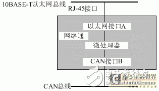
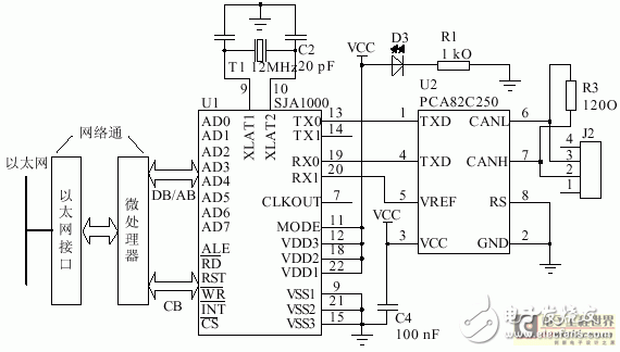
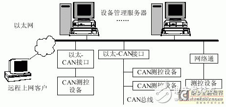
In large enterprise automation systems such as factories, substations, and intelligent buildings, as shown in Figure 1(a), Ethernet and PC are used in the upper management and production monitoring layers, while in the lower floor and on-site. Use fieldbus (such as rs-485/'target='_blank'>RS-485, CAN, lonWorks, foundation, etc.) and single-chip measurement and control equipment. The communication between the upper and lower layers is usually implemented by an industrial control machine plus an Ethernet card, plus an interface card on the PC slot or an EPP interface card of the parallel print port. This type of connection is costly and has a long development cycle. The interface card becomes the communication bottleneck between the upper and lower layers of the system. Once a failure occurs, the connection between the upper and lower layers is interrupted. To this end, as shown in Figure 1(b), we use the inexpensive "network communication" to form a single-chip based Ethernet-CAN gateway to replace the expensive industrial computer plus interface card, successfully implementing Ethernet and existing CAN bus network. The direct connection enables the connection between the management monitoring layer (Ethernet) and the production monitoring layer (CAN bus network). The upper and lower layers of data can be easily exchanged. Figure 1 Comparison of two distributed automatic control system structures More importantly, mature, stable, and inexpensive Ethernet has now spread to the grassroots of factories, workshops, and buildings. In the large enterprise automation system, it is not necessary to adopt the field bus and two-stage structure. The inexpensive Ethernet interface module “network communication†can be directly used to directly connect various measurement and control devices to the Ethernet to form a modern network control system. In the network control system, we use "network communication" to form a single-chip based Ethernet-CAN gateway. The structure is shown in Figure 2. "Network Communication" consists of Ethernet interface A and microprocessor. Adding CAN interface B on this basis constitutes the Ethernet-CAN gateway. Figure 2 Ethernet-CAN Gateway based on "Network Communication" (1) Ethernet interface A Ethernet interface A can use 10Base-T universal interface chip conforming to IEEE802.3 protocol, such as UM9003, RTL8019, etc., to complete the connection with Ethernet at the physical layer and data link layer. With the RJ-45 jack, you can attach directly to the Ethernet. (2) Microprocessor The microprocessor is responsible for controlling the Ethernet interface A chip and the CAN interface B chip. The TCP/IP communication protocol and the CAN protocol are stationed in the microprocessor, and the Ethernet protocol and the CAN bus protocol are converted, and the transparent transmission of the communication data of the interface A and the interface B is realized. Because the amount of data transmitted by the CAN bus is not large, the data transmission rate is not high, much smaller than the data transmission rate of the Ethernet. Therefore, in the Ethernet-CAN interface module, the data transmission bottleneck is on the CAN interface B. In the field of measurement and control, the amount of data usually transmitted is not large, and the data transmission rate is not high. Therefore, in this module, the microprocessor can be selected from a conventional single chip microcomputer such as 8031. (3) CAN interface B CAN interface B uses Philips' physical layer and link layer interface chips SJA1000 and PCA82C250. The microprocessor directly controls AD0~AD7, , ALE, RST and pin of SJA1000. The MODEL pin of SJA1000 is connected to the high level and works in Intel mode; the chip select pin is grounded and always in the strobe state, as shown in Figure 3. The operation of the SJA1000 by the microprocessor is mainly the operation of the register: on the one hand, the mode register (MOD), the command register (CMR), the status register (SR), the interrupt register (IR), the interrupt enable register (IEP) of the SJA1000, The bus timing registers (BTR0, BTR1), the output control register (OCR), and the clock division counter (CDR) are set and detected. On the other hand, the transceiver buffer is read and written to exchange data with the CAN device. Figure 3 Ethernet-CAN interface schematic Figure 4 is a flow chart of the microprocessor initializing, reading, and writing to the SJA1000. The microprocessor sends the command sent by Ethernet to the CAN measurement and control device by writing to the SJA1000; in turn, it will read the measured value or status of the CAN measurement and control device to the SJA1000 and send it out via Ethernet. Figure 4 Microprocessor CAN interface schematic Network distributed control requires an open, digital, multi-point communication control network. The field-based network distributed control system can be widely applied to the automation system to illustrate this point. Replacing the fieldbus network with Ethernet not only meets these needs, but also has many advantages. 1 There is no need to lay a CAN communication network to carry out information transmission between devices. Instead, it uses a widely available, inexpensive, standard Ethernet to transmit information. The establishment of such a measurement and control network is very fast. In theory, the number of nodes is not limited, the networking cost is low, and maintenance is easy. 2 In the data transmission, the address of each measurement and control device actually consists of two parts: the IP address of the “network communication†and the address of the CAN interface. In Ethernet, the CAN address of the CAN interface measurement and control device is transmitted together with the data of the IP packet in the "network communication" communication. 3 Features of high communication capacity with multi-master and multi-slave; hardware CRC check every frame, high reliability; communication message can be large or small, high efficiency; communication protocol TCP/IP is a global unified specification, easy to connect A large control network that is not geographically restricted. 4 The WWW (Word Wide Web) browser has a friendly and easy-to-use human-machine interface. The device management server uses a browser to detect and control different devices on the Ethernet, and uses the WWW publishing method to provide dynamic interactive web browsing to network clients. It is easy to implement a dispatch production management system or an office automation information system. 5 Because the communication data packet conforms to the TCP/IP standard, it can traverse the switch or router on the Internet. The remote Internet customer can easily query the status of each intelligent device and remotely control each smart device by using the WWW browser. In the enterprise automation system we designed and remodeled, the method of Figure 5 was adopted. All the original CAN measurement and control equipments are directly connected to the enterprise Ethernet through the Ethernet-CAN interface module, and some are still connected to the Ethernet through the CAN bus network; and the newly added equipment is directly connected to the Ethernet through the Ethernet interface module. There is no longer a need to lay a dedicated CAN communication network for information transfer between devices. Figure 5 Block diagram of a distributed control application system based on Ethernet On the Ethernet, all CAN measurement and control nodes form a virtual network segment. The CAN device management server is any control node in the enterprise Ethernet. The WIN NT server connected to the Ethernet can install the dedicated network management software to allow the legal engineers to remotely manage the CAN device and perform data with the CAN device through the Ethernet. Communication. In this way, Ethernet can completely replace the original CAN bus network. At the same time, the server uses the WEB publishing method to provide dynamic interactive browsing of web pages to network customers. With the development of industrial automation and office automation, in some occasions, the network of distributed control systems is becoming more and more large, and the fieldbus is more and more limited by geography, installation cost and load capacity. On the other hand, the rapid development of Ethernet, which is flexible, convenient, safe and reliable, and the popularity of the Internet, the broadband network has penetrated into homes, offices, hotels, factories and workshops, enabling people to live and work in various locations. Exchange information over the Internet. In this case, the use of cheap "network communication", the use of the Internet to replace the field bus, the original fieldbus distributed control system is easily converted into an Ethernet-based distributed control system, will be more and more widely application.
What is a Capsule Slip Ring?
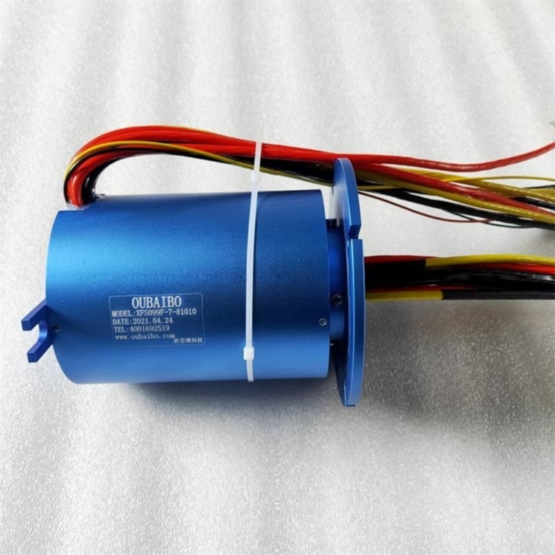
Capsule slip rings are a type of electrical connector that are used to transfer power and data between two rotating objects. They are commonly used in applications where there is a need to send or receive signals from a stationary object to a rotating one, or vice versa.
How Does it Work?
Capsule slip rings work by using a series of electrical contacts that rotate with the object on which they are mounted. These contacts are spaced evenly around the circumference of the ring, and as they rotate they make and break contact with corresponding contacts on the other object. This allows power and data to be transferred between the two objects without any interruption.
Advantages of Capsule Slip Rings
There are several advantages to using capsule slip rings in place of other types of electrical connectors.
For example, the rotation of the contacts causes them to be freely accessible and therefore free from dust and debris. This makes them ideal for applications where connector maintenance is often a problem.
Because the contacts are freely accessible, they can be readily replaced if a fault occurs. They also have very low electrical resistance, making them ideal for transmitting radio frequency signals. Because of the low resistance, this type of connector is often used in high-speed data transmissions.
This type of Conductive Slip Ring is similar to the shape of a hat. The brim part is a flange with a conductive slip ring. The function of the flange is to facilitate installation. It is connected to electrical equipment through the fixing hole of the flange. It can be firmly installed on the equipment. Therefore, the stator of the cap-type slip ring is generally fixed by the outer layer with a flange, and the inner part is the rotor with the inner shaft rotating. The stator and the rotor are not fixed, and the details will be different according to the installation method.
Capsule Slip Ring,Split Ring Motor,Slip Ring Motor Connection,Slip Rings In Synchronous Motor Dongguan Oubaibo Technology Co., Ltd. , https://www.sliprobs.com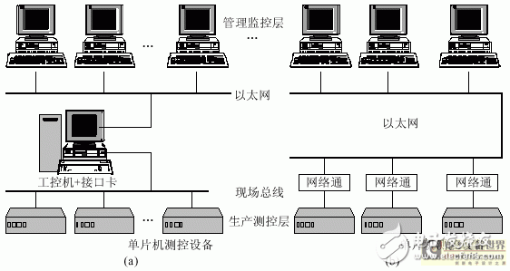

1 Overview