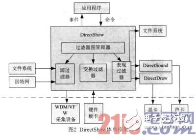
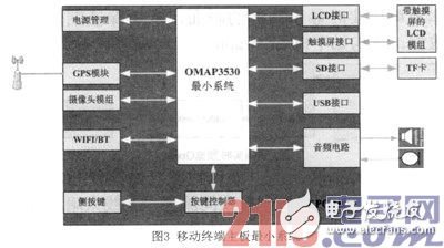
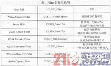
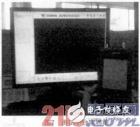
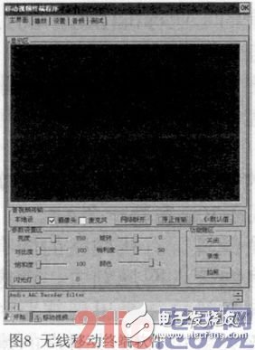
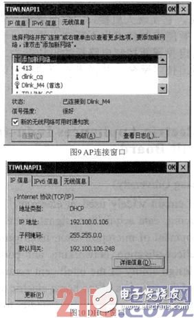
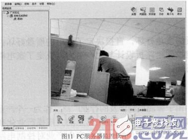
With the in-depth development of the power system reform, in order to improve economic efficiency and increase labor productivity, the State Grid is preparing to implement unattended operations in various substations. Nowadays, the rapid development of computer technology, network technology, and multimedia technology makes it possible to build this remote video surveillance system through the network. Most of the traditional monitoring systems need to be connected to the wired network to realize the monitoring function. There are some limitations in space and transmission methods, and the monitoring equipment cannot be comprehensive. Once an electrical accident is caused by natural disasters, improper operation, equipment aging and other problems, and the location of the failure is uncertain, after the repair personnel arrive at the scene, they often do not have suitable monitoring and management equipment, which makes the emergency repair command center unable to timely and accurately Collect, store and supervise real-time information on the operation site. With the development and popularization of wireless technologies such as WiFi, it is possible to transmit video data wirelessly. Utilizing the convenience of wireless network, the scene can transmit video to the command center anytime and anywhere, so as to better interact with the scene. Based on the strong demand of the current power monitoring system for the market in this field, it is proposed to design and develop a portable video transmission system. 1.1 System composition The system can be roughly divided into three parts: wireless mobile terminal, WiFi wireless transmission network and monitoring platform, using C/S architecture. As shown in Figure 1. (1) Wireless mobile terminal. The wireless mobile terminal is a handheld device similar to a PDA, which is flexible and convenient to use. The device comes with a camera, WiFi communication module, etc. The main functions of the terminal client software include: video signal collection, preview, transmission, and photography; system parameter settings (such as time, backlight, etc.); camera parameter settings (such as brightness, saturation, etc.). Mobile terminal software involves many functions and is difficult to implement, which is the focus of this article. (2) WiFi wireless network. After the video signal is collected, it is processed by the corresponding video coding technology, and the data is transmitted to the monitoring platform through the WiFi wireless network for real-time display and playback. (3) Monitoring platform. The monitoring platform is a PC server. By installing monitoring software, you can monitor and save the video images from the mobile terminal in real time. 1.2 Technical basis for system research (1) DirectShow technology. DirectShow is a member of DircctX. It provides a complete solution for multimedia applications with high performance requirements such as media file playback in various formats and audio and video capture on the Windows platform. In the development technology of DirectShow, a more important concept is the filter. The filter is at the core of the DirectShow technology. The core function of a DirectShow-based program is implemented by several filters. The filters are roughly divided into There are three types, namely Source filter, Transform filter, and Render filter. In a specific application, these three filters form a filter graph (Filter graph). ), a filter graph manager (Filtcr grap hmanager) manages all filters in this graph, and the application deals with the filter graph manager through events and commands to control all functions. The system framework of DirectShow is shown in Figure 2. (2) WiFi communication technology. The full name of WiFi is Wireless Fidelity, also known as the 802.11b standard, which is an industrial standard (IEE 802.11) for wireless network communications defined by 1EEE. The advantages of WiFi wireless transmission technology are reflected in: ·Easy to erect, eliminating the need for long-term wiring installation on site. ·Wide coverage, the radius of WiFi can reach about 300feet, which is about 100m. Generally, you only need to install one or more AP devices to solve the on-site network communication problem. According to the actual measured experience, an AP is generally installed at an interval of 30m. · Investment economy. The inherent shortcoming of wired networks is that they lack flexibility. In the planning of wired access networks, considering future development, a large amount of advance investment often results in low line utilization. The WiFi planning can be gradually expanded with the increase of users without rewiring, which has strong economic efficiency. ·The transmission speed is fast, up to 54Mbit/s, which fully meets the requirements of video data transmission. (3) Video coding and decoding technology. The video image data collected by the camera of the mobile terminal is quite huge. If it is not compressed, if you want to digitally transmit a frame of the original video image (for example, the output video pixel format of the camera of this system is 320×240, and each pixel occupies 16bit, the speed is 30 frames per second) The transmission capacity is required to reach 320&TImes;240&TImes;16&TImes;30=35.16Mbit/s. Therefore, it is unimaginable that uncompressed video is transmitted on a general communication network. The so-called video coding technology refers to a way to convert the original video stream into another video stream through a specific compression technology. At present, the most important coding and decoding standards in video streaming transmission are ITU's H. 263, H. 264, the MPEG series standards of the ISO Moving Picture Experts Group. In addition, Real-Networks' Real Video, Microsoft's WMV and Apple's QuickTIme are widely used on the Internet. 2.1 Wireless mobile terminal 2.1.1 Hardware design The mobile terminal adopts the Wince operating system, and the hardware platform is based on TI’s OMAP3530 embedded high-end CPU, with a main frequency of up to 600MHz. The system hardware architecture is shown in Figure 3. 2. 1.2 Client software design Client software design is the most important part of a wireless video system, and it is also a difficult point to implement. The software adopts MFC authoring tools and is based on the implementation of DirectShow framework, mainly including the following functions: (1) The realization method of the system parameter setting module. ·System backlight adjustment. The backlight adjustment function of the system is mainly realized by the interaction of the power management module and the backlight driver of the Wince system. Provides such as setting the brightness of the backlight, when to automatically turn off the backlight in the case of drone interaction, etc. ·Video file storage path. Taking into account the actual working environment, the real-time video saving path may be the flash path or the SD card path, which involves the setting of the file path. The implementation method is: by default, it is the flash storage path (\ResidentFlash). If the flash space is small and there is an SD card, it is recommended to set the SD card path (\Storage Card). After the next startup, it will display the path saved last time. ·System time setting. The display and setting of the system time are by calling the time setting program that comes with the wince system. (2) Implementation method of video control module. Constructing the correct Filter Graph is the key to successful software development based on DirectShow. After building the Graph, then use the relevant interface functions provided by the DirectShow component to add all the Filters in the graph, and connect the Pins connected to the Filter (Pin is the unit through which multimedia information in DirectShow flows, and the data flows in the Graph. Supported by the Pin exported by each Filter), and finally start Graph. ·Real-time transmission of video data. The original video data collected by the mobile terminal camera is compressed by H264 encoding and then transmitted to the remote monitoring platform through the TCP/IP network. Construct the Fil ter Graph as follows: ·Local real-time preview of video data. The staff not only need to transmit the video images captured on site to the command center in real time, but also need to display the current images locally in real time to ensure image consistency. Construct the following Filter Graph: · Instant photo function. The on-site situation is complicated and the environment is also very different. The video quality may be poor due to the dark construction at night, or the detailed observation of a faulty device on the site is required. At this time, the camera function is required. The mobile terminal adopts a high-resolution camera (OV3640, 3 million pixels, with flash), and the picture taken is very clear, which fully meets the requirements of use. Filter Graph is constructed as follows: In the software development process, many filters are involved, which correspond to unique GUID identifiers. Table 1 lists the main filter names and brief descriptions of their functions: 2.2 Monitoring platform The PC server-side monitoring software is relatively easy to implement and its functions are relatively simple. It mainly includes the decompression of video data. For the establishment of related Filter Graph, refer to the part of wireless mobile terminal, which will not be repeated here. In order to test the feasibility and correctness of the system, the following test platforms were built: one handheld mobile terminal, one wireless router (that is, AP), and one PC (server). The wireless router and PC server are in the local area network. The physical map of the test platform is as follows: 3.1 Video wireless real-time transmission and display The test process is as follows: ·First run the wireless terminal client software (as shown in Figure 8) and the PC-side server monitoring software. At this time, the monitoring software is waiting for the client to connect. ·Set up the mobile terminal WiFi connection; turn on the DHCP function and connect to the AP (Figure 9). ·After the AP is successfully connected, an IP address will be automatically assigned (Figure 10). · Establish a TCP/IP connection, and after success, transmit video data. The test result is shown in Figure 11. In the actual test process, with the AP as the center, moving around within the effective range (about 50m), the video can be transmitted and displayed smoothly, which meets the requirements of the field. At present, with the rapid development of embedded technology, digital video and wireless network technology, video surveillance technology is also becoming more mature and successfully used in the field of power system automation. This paper designs and develops a portable video transmission system based on embedded system Wince and WiFi wireless technology. It has the following characteristics: relying on handheld terminals to collect and transmit live images anytime and anywhere, highlighting portability; using WiFi wireless technology, convenient and fast; using TCP ï¼IP protocol transmits video data to ensure the reliability of transmission. With the mature application of wireless transmission technology in video surveillance systems, it will certainly enhance the safety and reliability of power operation and play an important role in the development of social economy. Wuxi Sunket New Energy Technology Co.,Ltd , https://www.sunketsolar.com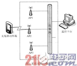


0 Preface