The basic principle of the DTXXX digital multimeter to measure capacitance is to utilize the capacitive reactance of the capacitor. Rectifier Diode(Standard Diode)
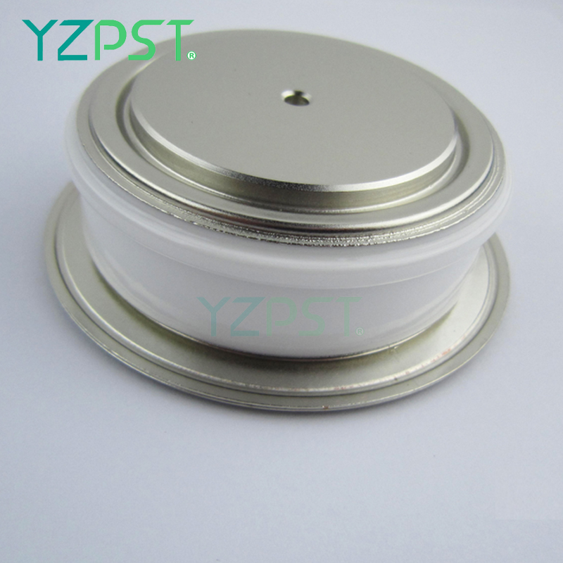
Rectifier Diode(Standard Diode) utilizes the unidirectional conductivity of the diode, which can convert the alternating current of alternating direction to a pulsating direct current of a single direction. Rectifier diode – diode designed for rectifying alternating current (mostly with low power frequency – 50 Hz at high power emitted during load). The main task of the rectifier diode is to convert AC voltage into DC voltage through application in rectifier bridges. The variant of rectifier diodewith the Schottky barrier is particularly valued in digital electronics.
Rectifier Diode,Standard Diode,High Power Rectifier Diode,High Voltage Rectifier Diode YANGZHOU POSITIONING TECH CO., LTD. , https://www.cndingweitech.com
The process is to apply a 400Hz sine wave to the two ends of the measured capacitance Cx, and use the generated capacitive reactance Xc to realize the conversion of the capacitance and the AC voltage, and then measure the AC voltage to obtain the Cx capacity.
The measurement circuit is divided into five ranges (of course you can also increase or decrease as needed), 2nF, 20nF, 200nF, 2uF, 20uF, and the measurement accuracy is 2.5%. The resolution is determined by the AC voltage measurement tool you use. The circuit is mainly divided into four parts. 
The first part is centered on A4 and forms a Wien-bridge circuit. When R8=R14, C3=C4:
This is a positive feedback circuit. Uo1 is fed back to the non-inverting terminal of A4 via R14 and C4. However, when the frequency is equal to the above frequency, the voltage of the non-inverting input of A4 is only 1/3 of Uo1. This also requires that the amplification factor of A4 must be greater than 3. , that is, 1+R13/R12>3, that is, R13>2R12. But this multiple cannot be too large, otherwise the sine wave may be deformed.
The second part is centered on A3 to form a reverse proportional operation circuit, which also acts as a buffer. Here, Uo1 is scaled down, and the ratio is (R10+VR1)/R11. Adjusting VR1 can change the scale.
The third part is centered on A1. The capacitor-AC voltage conversion circuit (C/ACV) is the same as the second part. The input resistance here is the capacitive reactance of Cx. Different ranges and feedback resistances are different. The table below shows the different Rf values ​​for different ranges. It can be seen that the maximum measured capacitance is equal to the product of Rf. 
The magnification is as follows: 
Since RC is equal, the amplification factor of the maximum range is equal, about 5.03. So Uo3=5.03Uo2. Because Uo2 is a certain value, the voltage of the output of each range is equal, which ensures that the accuracy of different quantities is the same. And, for the same range, the output voltage is proportional to the capacitance value Cx.
The fourth part is centered on A2 and forms an active bandpass filter with a center frequency of 400Hz to filter out other frequency interference. The final output voltage Uo4 is a 400Hz AC sinusoidal voltage whose amplitude is proportional to the measured capacitance Cx. With a meter that can measure a sine wave, its capacitance can be measured.
It should be noted that the measured results are in line with the capacitance, so you should adjust the scale according to your measuring instrument to get a direct reading.
