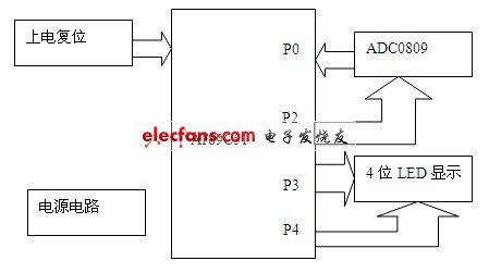
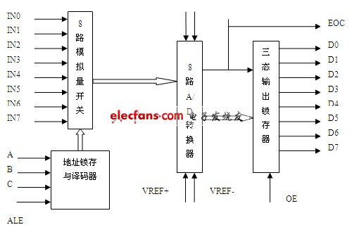
1 Introduction Due to the advantages of simple and practical, high reliability, good performance and price ratio, and small size, the single-chip microcomputer has been rapidly developed in various technical fields. Digital Voltmeter (Digital Voltmeter) is a digital measurement technology that converts continuous analog (DC input voltage) into discrete, discrete digital form and displays it. The traditional pointer voltmeter has a single function and low precision, which can not meet the needs of the digital age. The digital voltmeter of the single-chip microcomputer has high precision, strong anti-interference ability, strong expandability, convenient integration, and real-time communication with PC. . At present, digital voltmeters composed of various single-chip A/D converters have been widely used in the fields of intelligent measurement such as electronic and electrical measurement, industrial automation instruments, and automatic test systems, showing strong vitality. At the same time, various general-purpose and special-purpose digital instrumentation expanded by DVM have also raised the power and non-electricity measurement technology to a new level. This design focuses on the operation of a single-chip A/D converter and a microcontroller-based digital voltmeter. 2 overall design 2.1 Road plan ideas According to the system function requirements, it is decided that the control system adopts AT89S51 single-chip microcomputer , and the A/D conversion adopts ADC0809. In addition to ensuring the required functions, the system can also easily expand its functions. This article uses AT89S51 as the core component. AT89S51 is a low-power, high-performance CMOS 8-bit MCU with 4k Bytes ISP (In-system programmable) flash-ready program memory that can be repeatedly erased 1000 times. The device uses ATMEL. The company's high-density, non-volatile memory technology is compatible with the standard MCS-51 command system and 80C51 pin structure. The chip integrates a universal 8-bit CPU and ISP Flash memory unit. The AT89S51 is a powerful microcomputer. A cost-effective solution for many embedded control applications. Using NS's 8-bit sequential high-precision analog-to-digital converter ADC0809, ADC0809 is a CMOS with 8-bit A/D converter, 8-way multiplexer, and microprocessor-compatible control logic. Component. It is a successive approximation A/D converter that can interface directly with a microcontroller. The voltage taken is processed and then sent to the MCU through the P port of the MCU and then processed by the program, and the voltage value is displayed by the LED circuit. The single-chip microcomputer plus the peripheral serial port display circuit is composed of 74LS245 and digital tube triode. The device is manufactured using ATMEL's high-density, non-volatile memory technology and is compatible with standard 8051 instruction systems and pins. It integrates Flash program memory, which can be programmed in both online (ISP) and traditional methods, and a general 8-bit microprocessor in a single chip. ATMEL's powerful, low-cost AT89s51 microcontroller can provide you with many cost-effective Applications can be flexibly applied to a variety of control areas. 2.2 Design block diagram Figure 1 digital voltmeter system design 3 Design principle analysis 3.1 Single chip microcomputer AT89S51 AT89S51 single-chip microcomputer is a low-power, high-performance CMOS 8-bit single-chip microcomputer produced by American ATMEL Company. It contains 4K bytes of system programmable Flash read-only program memory. The device is manufactured by ATMEL's high-density, non-volatile memory technology. Compatible with standard 8051 instruction system and pins. It integrates Flash program memory, which can be programmed in both online (ISP) and traditional methods, and a general 8-bit microprocessor in a single chip. ATMEL's powerful, low-cost AT89S51 microcontroller can provide you with many cost-effective Applications can be flexibly applied to a variety of control areas. 3.2 Features of AT89S51 40 pins, 4k Bytes Flash on-chip program memory, 128 bytes of random access data memory (RAM), 32 external bidirectional input/output (I/O) ports, 5 interrupt priority levels 2 interrupt interrupted interrupts , 2 16-bit programmable timing counters, 2 full-duplex serial communication ports, watchdog (WDT) circuit, on-chip clock oscillator In addition, AT89S51 is designed and configured with an oscillation frequency of 0 Hz and can be set by software. Power saving mode. In idle mode, the CPU suspends operation, while the RAM timer counter, serial port, and external interrupt system can continue to work. The power-down mode freezes the oscillator and saves RAM data, stopping other functions of the chip until external interrupt activation or hardware reset. At the same time, the chip also has three package forms, such as PDIP, TQFP and PLCC, to meet the needs of different products. The main features are: ◠Compatible with MCS-51 microcontroller products ◠4K bytes in system programmable flash memory ◠1000 erase cycles ◠Full static operation: 0Hz-33MHz ◠32 programmable I/O lines ◠2 16-bit timers/counters ◠6 interrupt sources ◠Full-duplex UART serial channel ◠Low power idle and power down mode ◠Interrupt can wake up after power failure ◠Watchdog timer ◠Double data pointer ◠Flexible ISP programming (word or byte mode) ◠4.0---5.5V voltage working range 3.3 ADC0809 internal logic structure The eight-way digital voltmeter mainly uses the A/D converter. The process is to first use the A/D converter to sample the voltage values ​​of each channel to obtain the corresponding digital quantity, and then calculate the corresponding digital signal by the proportional relationship between the digital quantity and the analog quantity. Simulate the voltage value and then display the analog value through the display. The design assumes that the input voltage to be tested is eight, and the voltage value ranges from 0 to 5V. It is required to be displayed alternately on a 4-bit LED digital tube or in a single channel. The minimum resolution of the measurement is 0.0119V, and the measurement error of c is ±0.02V. ADC0809 is an 8-channel 8-bit ADC chip with eight analog switches, address latch and decode, 256 resistor ladder network, electronic switch tree, successive approximation register, comparator and 3-state output latch. Interface with the computer. Clock frequency = 1.26MHz, conversion time = 100μs, conversion error ≤ ± 1LSB, including 8 data selectors for 8 ADCs. 8-channel 8-digit binary code LSTTL level output, 28-pin package. The ADC0809 multiplexer can be connected to 8 analog channels, allowing 8 analog time-sharing inputs and sharing A/D converters for conversion. The tri-state output lock is used to latch the A/D converted digital value. When the OE terminal is high, the converted data can be taken from the tri-state output latch. The internal logic structure of ADC0809 is shown in Figure 3.1. Figure 2 Internal logic structure of ADC0809
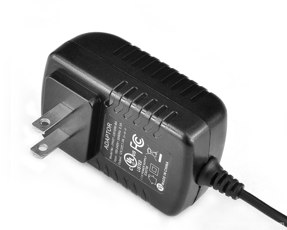
19V Plug in AC/DC Switching Power Supply were widely used for
any small power device, such as CCTV Cameras, wireless routers, LED strip, ADSL
cats, HUB, switches, security cameras, audio/video power supply. For 19V wall
mount power supply, the maximum output current is 1.89A,total 36W output. Our
power adaptor meets different certificates for different countries` request –
like UL list/CCC-CQC/ PES/SAA/C-TICK/CB/GB certificate. All our switching power
supplies were getting 2-hours burn-in test & 3KV high voltage test during
production.
19V AC DC Switching Power Adapter 19V AC DC Switching Power Adapter,19V AC DC 90W Switching Power Adapter Shenzhen Juyuanhai Electronic Co., Ltd. , https://www.powersupplycn.com

