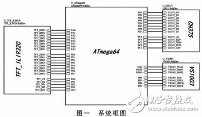
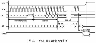
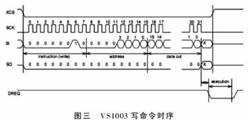
With the development of electronic technology, MP3 players are moving toward large capacity and miniaturization. But the integrated design of the player and memory makes it difficult for the MP3 to expand its capacity to accommodate more songs. Separating the player from the memory is another direction in which MP3 is currently evolving. This article describes a solution that uses AVR to control playback of a U disk USB file and decode it. This program has the functions of reading music labels, U-disk e-books, and snake games. It has commercial value. 1 Introduction to system functions The design mainly completes the reading operation of the music and text stored in the U disk, and can complete the playback of the MP3 music data and the display of the tag information in the U disk, thereby realizing the separation of the player and the memory, and completing on this basis. E-books, snake games and other functions. 2 system chip selection The design MCU chose ATMEL's ATmega64 as the main control chip. ATmega64 is a high performance, low power 8-bit AVR microprocessor with an advanced RISC architecture. 64K byte system programmable Flash, 2K byte EEPROM, 4K byte on-chip SRAM, 64 pins, 53 programmable I/O ports, SPI serial interface audio for master/slave mode operation The decoder chip selects the VS1003 produced by Finnish VLSI. VS1003 is a chip with MP3/WMA/MIDI audio decoding and ADPCM encoding. It contains a high performance, low power DSP core VS_DSP, working data memory, providing 5KB of instruction RAM and 0.5KB of data for user applications. RAM. A serial control and data interface, 4 general purpose I/O ports, a UART, a high quality variable sample rate ADC and stereo DAC, a headphone amplifier and ground buffer. USB communication chip selects CH375, CH375 is a universal interface chip of USB bus, supports USB-host host mode and USB-DEVICE/SLAVE device mode. At the local end, the CH375 has an 8-bit data bus and read, write, chip select control lines and terminal outputs, which can be easily hooked up to the system bus that controls the microcontroller. A protocol processor with built-in control transfer simplifies common control transfers. Low power mode is supported. 3 system hardware circuit design 3.1 MP3 decoder chip and ATmega64 hardware connection 3.2 CH375 and ATmega64 hardware connection In this design, CH375 works in HOST mode, and the eight-bit bidirectional data bus D0~D7 are respectively connected to PD0~PD7 of MCU to realize parallel transmission of data and commands. A0, RD, WR, INT, CS are connected to PC3~PC7 respectively. This connection makes it easy to hook the CH375 to various MCU system buses. 3.3 Color screen and ATmega64 hardware connection Color screen and MCU realize parallel data command transmission, connect 16-bit data command port with PA0~PA7 and PE0~PE7 of MCU, and select CS for color screen, strobe RS for data command, write strobe WR, read selection The RD and the reset RST are respectively connected to the PG0~PG4 of the MCU. 3.4 system connection block diagram shown in Figure 1 After the system is started, under the control of ATmega64, the data is first taken out from the U disk. If it is audio data, it is directly sent to VS1003 for decoding. After the VS1003 decodes the received data and converts it into analog audio, it outputs it through the power amplifier. . If the text data is received, the character format conversion is performed and displayed on the LCD screen. 4 system software design The system software design is mainly divided into VS1003 driver, CH375 driver, color screen driver and overall integration. (respectively: vs1003.cch375.c TFT_ili9320.c mp3_play.c ) 4.1 FAT file system management A FAT file system consists of four different parts. Reserved sector, FAT area, root directory area, data area. The first partition in the reserved area must be BPB, also known as the "boot sector", because it contains critical information that identifies the file system, and the computer will recognize the memory file format with this information, so it is important. The FAT area contains two file allocation tables for system redundancy, although it is rarely used, even for disk repair tools. It is a mapping table of partition information, indicating how the cluster is stored. The root directory area is a directory table that stores file and directory information in the root directory. It can exist anywhere in the partition under FAT32, but in earlier versions it always followed the FAT area. The data area is the area where the actual file and directory data is stored, which occupies the vast majority of the partition. 4.2 U disk reading Since the CH375 has a built-in protocol processor for controlling transmission, the U disk can be read by controlling the CH375 register. CH375 provides a file-level interface for USB storage devices in the C language subroutine. These application layer interface APIs contain common file-level operations that can be ported and embedded into commonly used microcontroller programs. The U disk file-level subroutine library of CH375 has the following features: support common file system, support multi-level subdirectories, support lowercase letters or long file names, support file open, new, delete, read and write, and search. The CH375 file-level subroutine library requires approximately 600 bytes of random access RAM as a buffer. All APIs of the file-level subroutine have operational status returns after the call, but there is not necessarily a response data. The main subroutines are as follows: (1) Initialize CH375 chip: CH375Init; (2) Open file: CH375Fileopen; (3) Enumerate or search for file: CH375FileEnumer; (4) Close file: CH375FileClose; (5) Read data from file in sector: CH375FileReadX ; (6) Write data to the file in units of sectors: CH375FilewriteX. 4.3 VS1003 read and write control The registers of the VS1003 are read in the following order, as shown in Figure 2. First, the XCS chip select is pulled low to select the chip, and then the 8-bit read operation code (0x03) and the 8-bit address are transmitted through the SI line. After the address is read by the VS1003 chip, the data on the SI will be ignored. The 16-bit data of the corresponding address will be removed from the SO line. The XCS needs to be pulled high when the data is completely removed. The registers of VS1003 must be written in the following order, as shown in Figure 3. First, the XCS chip select is pulled low, and then the 8-bit read operation code (0x02) and the 8-bit address are transmitted through the SI line. A 16-bit data word is sent. When the last bit is shifted in and the last clock has been sent, XCS must be pulled high to complete the write operation. 4.4 MP3 playback When the music player is executed, the ATmega64 chip first pre-fetches the tag information from the U disk. After analysis, the conversion from Unicode to GBK code is taken, and then the font is taken, and finally displayed on the LCD; after that, the data of the music file is taken and sent to With the VS1003 chip, the VS1003 starts decoding and emits audio signals on the audio interface. When the pause button is pressed, the data is paused, and the data loop is skipped when the previous song and the next song are skipped. 4.5 Other software design 1. Software design for music labels. The tags that can be read by this system are ID3V1 and ID3V2. When you want to distinguish these two tags, you can use the program to read the beginning and end of the music file, and use the identifiers "ID3" and "TAG" to distinguish which ones you have. a label. However, the text encoding in the tag also includes UNICODE, GBK, and the specific distinction should also look for the relevant identifier. 2. Software design for document reading. The GBK code will carry the ASC code, and the GBK code occupies two bytes. The ASC code occupies one byte. If every two bytes of the GBK code are taken in the process of taking the file, then the content is in the LCD. The display on the screen will be all garbled, especially when the page is turned up (the display of the document content on the LCD also needs to judge the carriage return and other characters, which will result in how many bytes are read on each page, how much is displayed. The bytes are different.) The final solution is to use an array to record how many bytes are displayed for each page flip (not how many bytes are read). 3. Display characters and Chinese characters on the TFT. For the TFT liquid crystal, no specific font is stored in the control chip, and it can only be the storage of the entire system. Moreover, the Unicode and GBK encoding of Chinese characters are not the same. The author stores the specific word library in the root directory of the USB flash drive to be read (the corresponding font file is ST16.BIN KT16.BIN). For the conversion of Unicode to GBK, the author also stores the conversion file under the root directory of the USB flash drive (the corresponding file is UNITOGBK.SYS). 5 Conclusion After testing, this design can read and play MP3 files in U disk, the sound quality is clear and sweet, no delay and frame skipping phenomenon. Can read the txt file in the U disk to implement the e-book function. The built-in Snake game can also be implemented smoothly. Since the design uses a separate player and memory, the storage space is not limited and the degree of freedom is large, which is more advantageous than the general MP3 player.
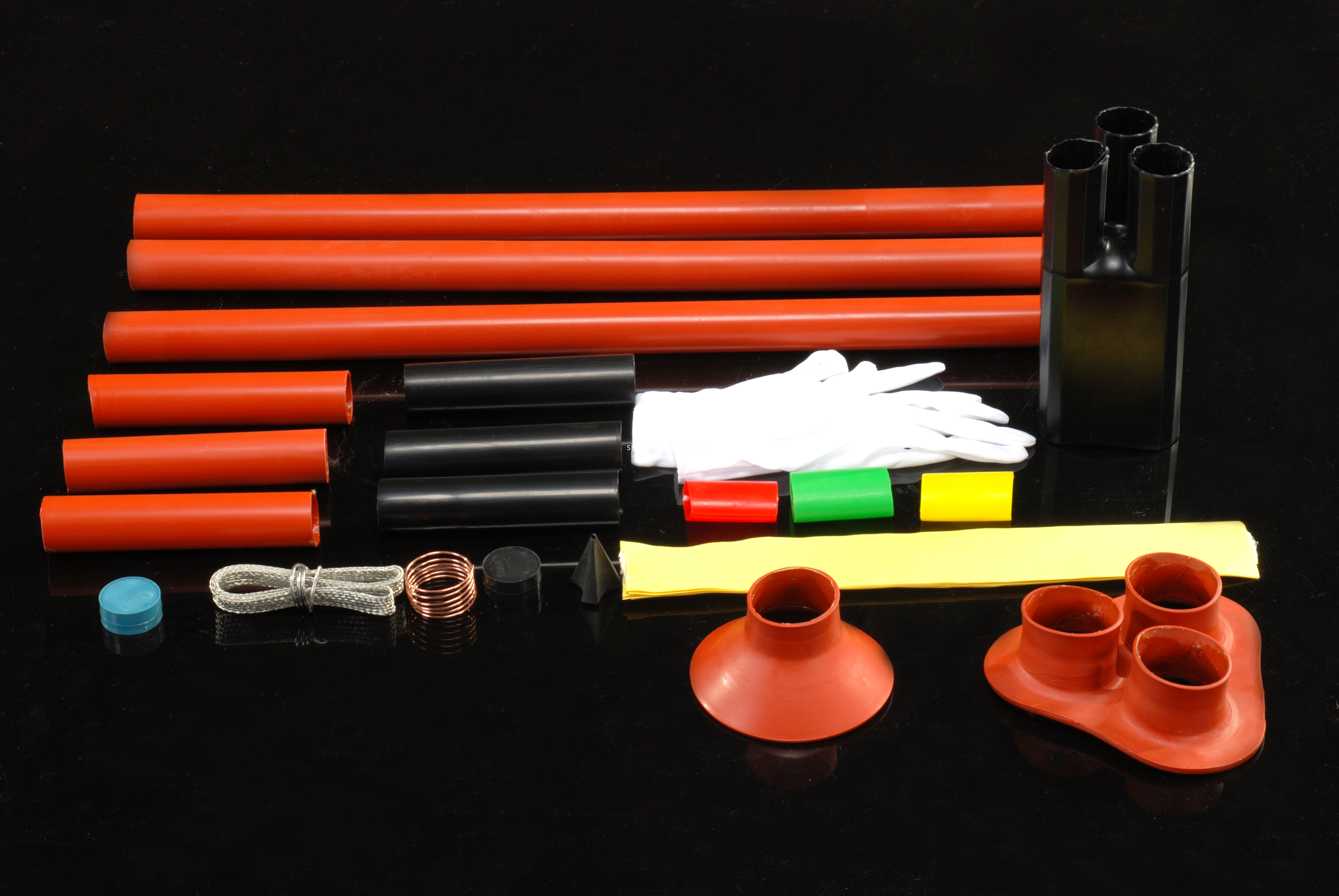
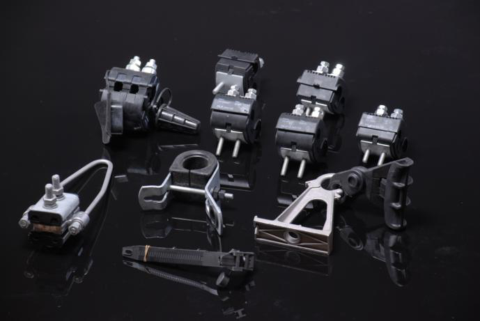
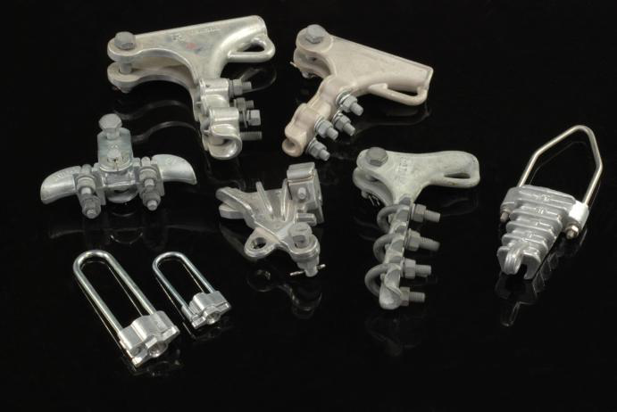
ABC Cable Fitting have a wide range of applications in low voltage insulated circuits, leading the branch connection from the main conductor; T-connection of low voltage insulation wire service and cable branch connection for the building distribution system. Abc Cable Fitting contain many types of products, such as insulaed cable clamp, Piercing Connector Clamp, Parallel Clamp , Suspension And Dead End Clamp ,round clamp and rod, Strain Clamp and Cable Lug .
We warmly welcome friends both domestic and abroad to visit our company, if you have any questions, please contact with us directly.
ABC Cable Fitting Insulated Cable Clamp,Abc Cable Fitting,Suspension And Dead End Clamp,Ground Clamp And Rod FUZHOU SINGREE IMP.& EXP.CO.,LTD. , https://www.cninsulators.com
The VS1003 uses synchronous serial bus SPI communication. The ATmega64 integrates the SPI bus controller internally, so the SCLK, MOSO, and MOSI can be directly connected to the SPI control pin of the MCU. In addition, XCS, XRES, DREQ, and XDCS are respectively connected to PB4~PB7, and the control of the decoding chip can be completed. 