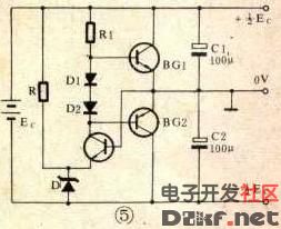
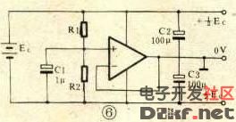
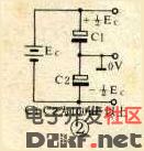
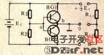
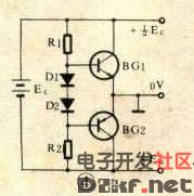
In the circuit of the drawing, the time base circuit 555 is connected to an unsteady circuit, and the square pin has an output frequency of 20 kHz and a square wave with a duty ratio of 1:1. When pin 3 is high, C4 is charged; when low, C3 is charged. Due to the existence of VD1 and VD2, C3 and C4 are only charged and not discharged in the circuit. The maximum charging value is EC, and the B terminal is grounded. At both ends of A and C, the dual power supply of +/-EC is obtained. The output current of this circuit exceeds 50mA. Changing the two resistors in Figure 1 to two large capacitors becomes the circuit shown in Figure 2. This circuit power consumption is reduced to zero, which is suitable for the case where the load of the positive and negative power supplies is equal or approximately equal. The circuit of Figure 3 is based on the addition of two transistors on the basis of Figure 1, which enhances the load carrying capacity of the circuit. The output current depends on the maximum collector current ICM of BG1 and BG2. The feedback loop can keep the positive and negative power supplies basically symmetrical when the two loads are different. For example, when Ub falls due to load unequal, Ua does not change (R1, R2 divided voltage supplies a constant Ua), BG1 is turned on, BG2 is turned off, and RL2 flows through a part of BG1, which causes Ub to rise. When RL1 and RL2 are equal, both BG1 and BG2 are in an off state. R1 and R2 can be made larger. The circuit of Figure 4 in turn improves the circuit of Figure 3. The addition of two biasing diodes causes the two transistors to deviate from the dead zone, enhancing the feedback effect, resulting in better symmetry and stability of the dual power supply. D1 and D2 can also be replaced by resistors of several tens to several hundreds of ohms. In the circuit of Figure 6, the op amp is connected to a voltage follower, and the output current depends on the load capacity of the op amp. For larger output power, a power amplifier manifold with improved open-loop gain, such as the TDA2030, can be used. This circuit is simple, but the performance is better than the previous circuit. Self Fusing Rubber Tape,Scotch Self Bonding Electrical Tape,Self Fusing Tape,Rubber Tape Self Fusing Longkou Libo Insulating Material Co.,Ltd. , https://www.liboinsulation.com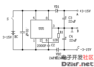
Here are a few single-supply-to-dual-supply circuits. Figure 1 shows the simplest conversion circuit. The disadvantage is that the resistance value selected by R1 and R2 is small, and the power consumption of the circuit itself is large: the load capacity is too weak when the resistance value is large. This circuit is not practical. 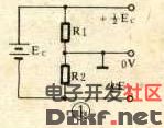
The circuit of Figure 5 has better symmetry and stability than the circuit of Figure 4. It replaces R2 in Figure 4 with a Zener and a triode to further enhance the feedback. 