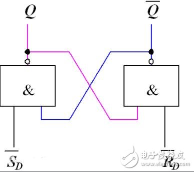
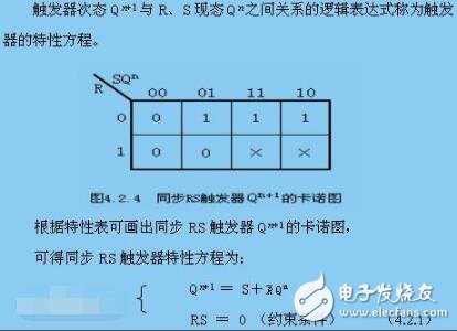
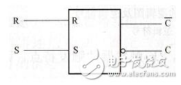
RS flip-flops are an essential part of the various other functional triggers. Also known as the basic RS trigger. The structure is to cross-connect the input and output ends of two NAND gates or NOR gates G1 and G2. The basic RS flip-flop can be constructed by cross-connecting the input and output terminals of two NAND gates or NOR gates G1 and G2. The logic circuit is shown in the right figure and is an RS flip-flop composed of two NAND gates. It has two inputs R, S and two outputs Q, Q non. The logic equation for the basic RS trigger is: Constraint equation: S'+R'=1 obtains its four inputs and outputs according to the above two equations: S'=0, R'=1: Regardless of the state of the trigger, since S=0, then Q=1, Q is non=0, and the trigger is in the “1†state (or set state). The state of the flip-flop is determined by S, and S is called the direct set terminal. S'=1, R'=0: Regardless of the state of the trigger, since R=0, then Q=0, Q is not=1, and the trigger is in the “0†state (or reset state). The state of the flip-flop is determined by R, which is called the direct reset terminal. S'=1, R'=1: The trigger remains unchanged. S'=0, R'=0: The state of the trigger cannot be determined at this time. Generally this is not allowed, so the inputs S and R of the flip-flop cannot be 0 at the same time. As mentioned above, when the two inputs of the flip-flop are added to different logic levels, its two outputs Q and Q do not have two complementary stable states. The state of the Q terminal of the flip-flop is generally specified as the state of the flip-flop. The trigger is usually called a certain state, and actually refers to the state of its Q terminal. When Q=1 and Q is not 0, the trigger is said to be in the 1 state, otherwise the trigger is in the 0 state. R=1, S=0, set the trigger to 1, or set. Since the decision condition for setting is S=0, the S terminal is said to be set to one end. When R=0, S=1, the trigger is set to 0, or reset. Similarly, the R terminal is called the 0 terminal or the reset terminal. If the flip-flop is originally 1 state, to make it into the 0 state, the level of the R terminal must be changed from 1 to 0, and the level of the S terminal is changed from 0 to 1. The input signals (low level) added here are called trigger signals, and the conversion process caused by them is called flipping. Since the trigger signal here is a level, this type of flip-flop is called a level control flip-flop. From a functional point of view, it can only be set and set by 0 under the action of S and R, so it is also called a set 0 trigger, or a set reset trigger. Its logical symbol is shown in Figure 7.2.1(b). Since setting or setting the trigger signal is active low, both the S and R terminals are drawn with small circles. 3. When the RS end is invalid, the trigger status remains unchanged. When the trigger is in the state, the input terminal is added with a non-active level (high level). When the flip is triggered, a negative pulse is required to be added to an input terminal. For example, a negative pulse is applied to the S terminal to set the flip-flop. After the pulse signal returns to the high level, the flip-flop remains in the same state, which is equivalent to storing the level signal at a certain point on the S-end, which embodies the memory function of the flip-flop. 4. When the RS terminal is valid, the trigger status is undefined. Under this condition, the outputs Q and Q of the two NAND gates are not all 1. After both input signals are simultaneously removed (returned to 1), the delay time of the two NAND gates cannot be determined. The state cannot be determined to be 1 or 0, so this condition is called an indeterminate state, and this should be avoided. From another point of view, just because the R and S ends are set to 0 and both are active low, the two cannot be 0 at the same time. In addition, the input and output cross-connections of the NOR gate can also be used to form a set and set trigger. The logic diagram and logical symbols are shown in Figure 7.2.2(a) and 7.2.2(b), respectively. The trigger signal of this flip-flop is active high, so there are no small circles at the S and R ends of the logic symbol. The RS flip-flop consists of two NAND gates, and the line form is shown. The RS flip-flop has two inputs, called the R terminal (set to the "0" terminal) and the S terminal (set the "1" terminal). RS flip-flop has two outputs C and Figure RS trigger 1. When the R terminal is invalid (1), when the S terminal is valid (0), then Q=1, Q is non=0, and the flip-flop is set to 1. 2. When the R terminal is valid (0) and the S terminal is invalid (1), then Q=0, Q is not =1, and the trigger is set to 0. 3. When the RS end is invalid (0), the trigger status remains unchanged. 4. When the RS terminal is valid (1), the trigger status is undefined. There is a difference in the priority when the 'S' is set and the 'R' is reset at the same time. When the RS flip-flop and the reset signal are both 1, the output is 1, and the set priority is given; When the SR flip-flop and reset signal are both 1, the output is 0 and the reset takes precedence. The set priority trigger is a set priority latch. The output is true when both the set signal (S1) and the reset signal (R) are true. The reset priority trigger is a reset priority latch. When both the set signal (S) and the reset signal (R1) are true, the output is false. Set priority trigger instruction (SR), reset priority trigger instruction (RS) Then it can be understood that SR is set first. Explosion Proof Temperature Sensor
The model of explosion-proof temperature sensor is wzpk-22i-b, which is made of stainless steel and has explosion-proof performance. If you want to conduct reliable temperature measurement, you first need to select the correct temperature instrument, that is, the temperature sensor. Thermocouple, thermistor, platinum resistance (RTD) and temperature IC are the most commonly used temperature sensors in testing.
The changes of physical parameters with temperature include expansion, resistance, capacitance, electromotive force, magnetic properties, frequency, optical characteristics, thermal noise and so on. With the development of production, new temperature sensors will continue to emerge.
Explosion Proof Temperature Sensor,Temperature Pressure Sensor,Explosion Proof Pressure Sensor,New High Temperature Pressure Sensor Taizhou Jiabo Instrument Technology Co., Ltd. , https://www.jbcbyq.com
![]() (Note: Take the RS latch composed of NAND gates as an example) (active low)
(Note: Take the RS latch composed of NAND gates as an example) (active low) 
![]() . When the C terminal is high, it is called the trigger is in the "1" state; when the C terminal is low, the trigger is in the "0" state. Under steady working conditions,
. When the C terminal is high, it is called the trigger is in the "1" state; when the C terminal is low, the trigger is in the "0" state. Under steady working conditions, ![]() The level with C is always the opposite. The "1" of the flip-flop is usually implemented by setting a "1" end S plus a negative pulse; setting the flip-flop to "0" is performed by setting a "0" end R plus a negative pulse. The total demand trigger is constantly flipped between 0 and 1 states, then the 0 and set 1 signals must be alternately sent to the two inputs of R and S. In order for the trigger to work reliably, it is required that the negative pulse width applied to the input terminal must be greater than the delay time of the two non-gate flips, otherwise normal triggering cannot be achieved.
The level with C is always the opposite. The "1" of the flip-flop is usually implemented by setting a "1" end S plus a negative pulse; setting the flip-flop to "0" is performed by setting a "0" end R plus a negative pulse. The total demand trigger is constantly flipped between 0 and 1 states, then the 0 and set 1 signals must be alternately sent to the two inputs of R and S. In order for the trigger to work reliably, it is required that the negative pulse width applied to the input terminal must be greater than the delay time of the two non-gate flips, otherwise normal triggering cannot be achieved. 