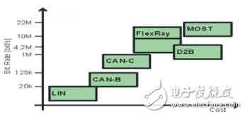
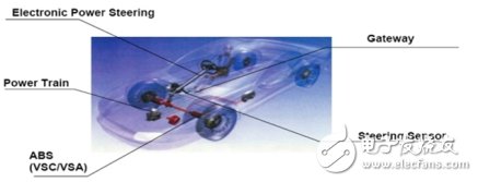
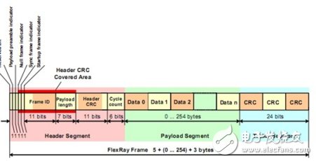
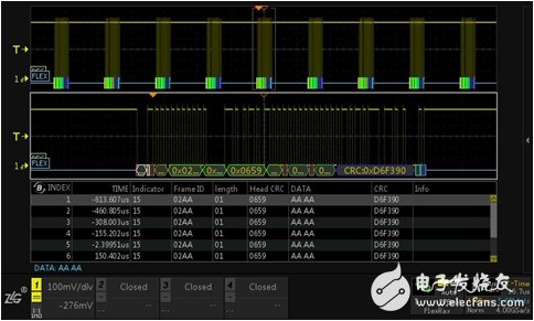
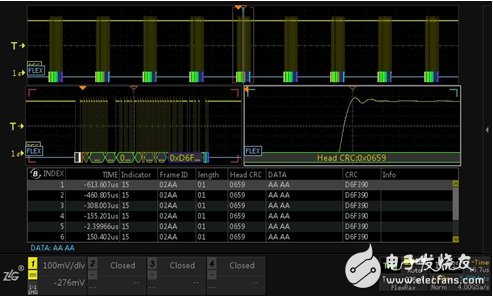
The FlexRay communication protocol is a high-speed automotive bus system with fault tolerance. It has been maturely used in the electronically controlled damping and main control suspension systems of the BMW X5. Here we will drink everyone to understand the FlexRay protocol and the corresponding decoding scheme. FlexRay is a high-speed deterministic, fault-tolerant automotive bus system. In most cars today, data exchange is mainly carried out via the CAN bus. The emergence of new x-by-wire system design ideas has also led to an increasing demand for information transmission speed, especially fault tolerance and time certainty. FlexRay meets these new requirements by passing information in defined time slots, as well as fault tolerance and redundant information transfer on both channels. The FlexRay topology can be divided into single channel and dual channel, including single channel bus type, single channel star type, single channel hybrid type and dual channel independently selectable topology. Figure 1 shows a single-channel bus type, and Figure 2 shows a two-channel topology. Figure 1 Single channel bus topology Figure 2 Dual Channel Bus Topology · FlexRay physically communicates over two separate buses, with a total data rate of up to 20 Mbit/s; · FlexRay has reliability features, especially its redundant communication capability, which enables complete network configuration replication and progress monitoring through hardware; FlexRay supports a variety of topologies such as bus, star, and hybrid topologies. Figure 3 Comparison of data rates for each protocol Although FlexRay itself does not ensure system security, it can support the design of a safety-oriented system such as the X-by-Wire system. Figure 4 FlexRay application system A data frame consists of a frame header, a valid data segment, and a frame tail. As shown in Figure 5: Figure 5 FlexRay data frame · Frame header 1. Reserved bits (1 bit) to prepare for future expansion; 2. The preamble indication (1 bit) of the load segment indicates the vector information of the load segment of the frame; 3. Empty frame indication (1 bit), indicating whether the data frame of the load segment is zero; 4. Synchronization frame indication (1 bit) indicating that this is a synchronization frame; 5. The start frame indication (1 bit) indicates whether the node transmitting the frame is a start frame; 6. Frame ID (11 bits) indicating the ID assigned to each node during system design; 7. Valid data length (7 digits) indicating the length of valid data; 8. Head CRC (11 bits) indicating the CRC calculation value of the sync frame indicator and the start frame indicator; 9. Cycle (6 digits). Indicates the period count of the node that transmitted the frame during the frame transfer time. · Effective data section 1. The data part is represented by data0, data1... in the figure; 2, information ID; 3. Network management vector. · End of frame There is only a single data field, the CRC part, including the frame header CRC and the CRC of the data frame. Relying on the powerful computing platform of the ZDS4054 Plus oscilloscope, the decoding function of the FlexRay protocol is available as standard. It can decode 512M full-memory FlexRay data and monitor vehicle communication signals. The information of each frame can be viewed in the event table, as shown in Figure 6 below: Figure 6 Flexray bus decoding Perform anomaly analysis on long-term monitoring data, and use the dual ZOOM multi-window display function in the zoom mode of the oscilloscope to perform multi-window abnormality monitoring and analysis on the signal, and analyze one data frame or one. The rise time of the rising edge is analyzed and measured, and the data changes in the event table can be observed in real time, as shown in Figure 7 below. Figure 7 Flexray detail analysis REMOTE CONTROL SOCKET
Programming Instructions
•Press any ON switch on the Remote Control for approximately 2 seconds and the Remote Socket(s) learn the code. The LED will stop flashing top confirm the codehas been accepted. Remote Control Plug Socket,Remote Controlled Mains Outlet,Remote Control Plug Adapters,Remote Control Sockets,Remote & Smart Controlled Sockets,Electric Sockets Plus Remote Control NINGBO COWELL ELECTRONICS & TECHNOLOGY CO., LTD , https://www.cowellsockets.com

Important Safeguards
When using any electrical appliance, in order to reduce the risk of fire, electric shock and/or injury to persons, basic safety precautions should always be follow8d. including:
• The appliance is for household and indoor use only.
• Before plugging in. check that the voitage on the rating label is the same as the mains supply.
• To protect against electric shock, do not immerse any part of the product in water or other liquid.
• This socket is intended for use by competent adults only and children should be supervised at all times.
• Do not use the socket for other than its intended use.
• This socket can be used by children aged from 8 years arxl above and persons with reduced physical, sensory or mental capabilities or lack of experience and knowledge if they have been given supervision or instruction concerning use of the appliance in a safe way and understand the hazards involved. Children shall not p<ay with the appliance Cleaning and user maintenance shall M be made by children without supervision.
• Children of less than 3 years should be kept away unless continuously supervised.
Children from 3 years and less than 8 years shall only switch on/off the appliance provided that it has been placed or installed in its intended normal operating position and they have been supervision or instruction concerning use of the appliance in a safe way and understand the hazards involved. Children aged from 3 years and less than 8 years shall not plug in. regulate and clean the appliance or perform user maintenance.
• Don't use this socket in the immediate surroundings of a bath, a shower or a swimming pool.
• In case of malfunction, do not try to repair the socket yourself, it may result in a fire hazard or electric shock
Do Not Exceed Maximum a680W
Place the LR44 batteries provided into the compartment in the back of the Remote Control, please insert as sho*/m in the back of the compartment to ensure the polarity is correct.
• Plug the Remoce Socket$($)lnto the wall socket(s) and switch on the mams supply, the red LED will flash every second.
• If the LED is not flashing press & hold the manual ON/OFF button for 5 seconds until it Hashes
• Any number of Remote Sockets can be programmed to one Remote Control ON button to create multiple switching.
• To programme o<her Remote Sockets on different Remote Control ON buttons repeat the prevous steps
• If the mains supply is turned off the Remote Sockets v/ill lose their code and it wil be necessary to re-pcogramme.
Operation:
• Plug your appliance(s) into the Remote Socket(s)
• Press the programmed ON or OFF button on the Remote Control to control the Remote Socket.
♦ The Remote Sockets can also be operated manually using its ON/OFF Button Trouble shooting
If a Remote Socket does not react to the Remote Control please check the followng:
♦ Low battery in tbo Remote Control
• Distance too large between the remote control and the recerver (ensure the range distance is no more than 20 clear Metres) and free from obstacle that may reduce the distance.
• If programming has not been successful, tum the power off and back on then follow the programming steps above.
How to decode
• Press the manual ONX)FF button for 5 seconds until the red LED flashes once per
second to confirm de-coding is successful
♦ Press the ALL OFF switch on the Remote Control for more than 3 seconds, the LED
flashes once per second to confirm (decoding successful.
Voltage: 240V-/50HZ
Max power rating: 3680W max.
Remote frequency:
Remote range:
Battery Type:
433.92MHz
230 Metres
Button Cell 2x1.5V LR44 =
Please check with your local waste management service authority regarding regulations for the safe disposal of the batteries. The batteries should never be placed G municipal waste.
Use a battery d^posal facility if available
M
For eioctncal products sold within the European Community. At the end of the electrical products useful life, it should not be disposed of wth household waste. Please recycle faaMies exist. Check with your Local Authonty or retailer for recycling advice.
C€