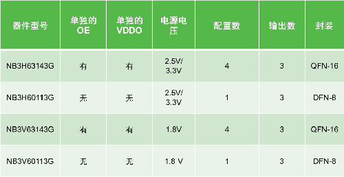
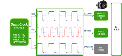
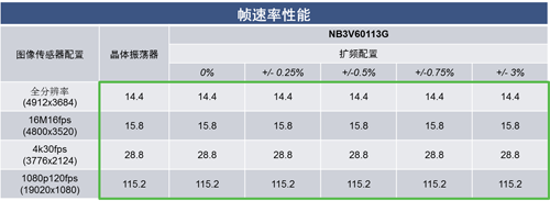
Clocks are a key element in electronic systems, and their performance is critical to the stable operation of the entire system. OmniClock, a highly customizable, one-time programmable clock generator family from ON Semiconductor, is flexible enough to be used in any programmable clock device on the market for wearables, smartphones, cameras, e-books, portable electronics Wide range of applications such as the Internet of Things, with small size, low power consumption, low cost, and improved crosstalk/jitter performance. OmniClock Series Features and Design Advantages The OmniClock family supports any output frequency from 8 kHz to 200 MHz and has three single-ended clock outputs (LVCMOS/LVTTL) that can be combined into one differential output (LVPECL, LVDS, HCSL / CML), allowing designers to replace many Crystals and / or oscillators reduce overall system cost. For example, the NB3H63143G can provide a 50 MHz, 125 MHz, and 48 MHz clock to the CPU core, physical layer, and CPU core to achieve the best master clock (BMC) algorithm, or both a single-ended 50 MHz and a differential 156.25 MHz. (LVPECL) Clock to Control Panel Complex Programmable Logic Device (CPLD) and Ethernet; and NB3V60113G, which provides a 25 MHz ± 0.125 % clock to the CPU core of a Solid State Drive (SSD) module, or a 27 MHz ± 0.5% of the clock to the MCLK master clock of the CMOS sensor. OE: Output enable VDDO: output voltage Table 1. The full range of OmniClock generators from ON Semiconductor 1 . Provides highly customizable flexibility OmniClock is a fully customizable device with programming software Clock Cruiser. Configurable parameters include output frequency, output type, drive current, output pin, internal load capacitance, supply voltage, output voltage, reference input, control pin, phase-locked loop (PLL) bypass characteristics and spread spectrum configuration, etc., in the system test process, can quickly switch between device configurations, the best performance of the architecture. In addition, designers can store up to four independent configurations to one-time programmable memory (OTPM), making it easy to enable configuration when output requirements are similar, reducing development time and inventory. 2 . Improve system reliability Using a crystal to generate a clock signal can cause a number of problems, such as board layout and routing, temperature and voltage, long startup times, and the need for additional components such as load capacitance. By replacing the crystal and mechanical components with the OmniClock generator, system failures can be reduced and system reliability can be improved. 3 . Reduce system EMI ( electromagnetic interference) peaks Wiring between components on the board can create potential noise and EMI. The OmniClock internal PLL provides fully programmable spread-spectrum frequency modulation to address system EMI peak interference through a variety of spread-spectrum configurations. For spread spectrum, designers can choose the type of spread spectrum such as non-spreading, center spread or downlink spread, with percentage deviations such as center spread from ± 0.125% to ± 3% of 0.125% steps, or 0.25 for downstream spread spectrum. The % step is -0.25% to -4%, and the frequency modulation can be any value between 30KHz and 130KHz. Spread-spectrum modulation is based on the PLL output, and operation in PLL bypass mode will not be affected. This requires a trade-off between the input clock frequency and the desired spread spectrum configuration. 4 . Save space and reduce costs Because OmniClock eliminates crystal and crystal oscillators, load capacitors, saves board space, simplifies bill of materials, reduces complexity and system cost, and is available in very small QFN-16 and DFN-8 packages. Very small application requirements in space. 5 . Low power consumption Low power consumption is a key advantage of the OmniClock family, extending battery life in end products such as portable consumer devices. OmniClock for USB video cameras to improve crosstalk/ jitter USB video cameras typically require multiple reference clocks for image sensors, image coprocessors, and USB controller modules running at different frequencies, using clock generation and buffers for system design to improve crosstalk/jitter and provide better layout Flexibility and easy system upgrades at an advantageous cost. A single OmniClock device is configured to support the three frequencies required for a USB video-like camera: a 19.2 MHz clock to the AR1820HS 18 megapixel image sensor, a 48 MHz clock to the AP1302 image coprocessor, and a 19.2 MHz clock to a USB control Replace the crystal and crystal oscillator. The customizable spectrum configuration makes this family of devices suitable for EMI-sensitive applications without sacrificing imaging performance. Its flexibility further supports the manufacturing process by verifying dynamic password (OTP) parameters through programming software, while its small package design reduces board complexity and cost. Figure 1. OmniClock provides three frequency clocks for USB video-like cameras Due to the long flat cable used in the design of the network camera system, the pixel clock produces EMI harmonic peaks. The OmniClock spread-spectrum configuration solves application-sensitive EMI spikes without compromising imaging performance without the need to modify hardware. Taking NB3V60113G as an example, as shown in Table 2, for image sensors with full resolution, 16M16fps, 4k30fps, 1080p120fps, the crystal oscillator frame rates are 14.4 fps, 15.8 fps, 28.8 fps, 115.2 fps, and NB3V60113G is 0. Spreading from % to +/- 3%, the frame rate remains the same. Table 2. OmniClock Spread Spectrum Configuration Does Not Reduce Imaging Performance Design considerations In order to have good clock signal integrity to minimize data errors, it is necessary to reduce signal reflection. The reflection coefficient is zero only when the source impedance is equal to the load impedance. It is therefore necessary to match the impedance to reduce signal reflection. The impedance difference can be minimized by adding a series resistor near the output pin. To protect the device from system power supply noise, place a 0.1 uF and a 2.2 uF decoupling capacitor on the board as close as possible to the VDD pin. The board traces and ground vias to the VDD pin should be as thin and short as possible. All VDD pins should have decoupling capacitors. Differential signals such as LVDS have the inherent advantages of common-mode noise rejection and low noise, support fast switching speeds, and consume less power than other differential signaling standards. Fan-out LVDS buffers can be used as extensions to provide clock signals to multiple LVDS receivers. Drive multiple point-to-point links to the receiving node. to sum up The OmniClock family offers the most functionality and flexibility for any programmable clocking device on the market. The devices accept a range of crystal or reference clock input frequencies to produce a differential output (LVPECL, LVDS, HCSL, CML) plus a single-ended , or three-way single-ended LVCMOS output at a user-defined frequency, supporting any output frequency from 8 KHz to 200 MHz, replacing crystals and / or oscillators, saving board area, reducing overall system cost, surpassing the complete use of discrete crystals System that improves crosstalk/jitter, enhances system reliability, greatly simplifies board design, and enables customers to meet their system's low power requirements, shortening delivery time compared to crystals, and customizable spread-spectrum configurations for EMI Sensitive application. Switch Cabinet,Innovative Low Voltage Switchgear Cabinet,Switch Rack Cabinet,Switch Cabinet Wall Mount Tianhong Electric Power Technology Co., Ltd , https://www.tianhongtransformer.com

