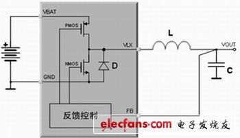
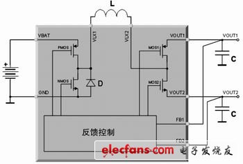
introduction In modern applications, traditional low-dropout regulators (LDOs) are gradually being replaced by switching power supplies (SMPS). Although LDO is a low-cost and rugged power solution, it consumes a lot of power. More and more portable equipment manufacturers, such as digital camera, mobile phone, and PDA manufacturers, are studying the feasibility of replacing LDO with more efficient solutions. The size of the switching solution, the physical size of the power supply, is usually an obstacle that these manufacturers cannot overcome. STw4141 is an innovative switching power supply that can generate two independent output voltages using only one external coil. Because of its inherent switching characteristics, the efficiency of this chip is very high, and the number of external components required is very small. The efficiency of this product is comparable to that of two independent switching power supplies, and its size is equivalent to two independent LDO power supplies. Therefore, it is possible to replace a linear power supply in a portable device or reduce the physical size and cost of a switching regulator. working principle First briefly understand the traditional buck DC-DC converter, STw4141 innovative dual output topology is derived from this design. Figure 1 is a circuit diagram of a simple buck converter, and Figure 2 is the waveform of its coil current. The buck converter topology components include a power stage composed of PMOS and NMOS, a coil L, an output capacitor C, and a feedback control loop. PMOS and NMOS switch in reverse at a frequency of 1 / T, with a duty cycle of D1. When the PMOS transistor is turned on, the coil current starts to rise, and the slope is: (1) When the NMOS transistor is turned on, the coil current starts to decrease, and the slope is: Figure 1 Buck topology (2) During steady state, the following conditions must be valid: (3) (4) Formula 3 means that the coil current IL at the beginning of each clock cycle must be equal to the coil current IL at the end of each clock cycle (otherwise the system is not in a steady state). From this condition, we can derive the duty cycle formula of the buck converter. (5) Equation 4 means that the total power generated by the coil must be equal to the total power consumed by the load, assuming that all switches and RDSon losses are ignored. Figure 2 Coil current waveform For the dual output topology, in the STw4141 voltage regulator, the current generated by the coil is distributed to the two output terminals, and the load current obtained from these two output ports can (in fact always) be completely uncorrelated. Therefore, the steady-state condition of Equation 4 must be rewritten as: (6) where Iload1 is the current drawn by the load from output 1, and Iload2 is the current drawn by the load from output 2. Bulkhead Lamp,Led Bulkhead Lamp,Round Bulkhead Light,Bulkhead Ceiling Light Changxing Fanya Lighting Co.,Ltd , https://www.fyledlights.com
