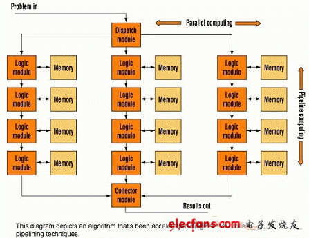
Hardware designers have begun to use FPGA technology in the design of high-performance DSPs, because it can provide 10-100 times faster calculations than PC or single-chip solutions. In the past, software developers unfamiliar with hardware design had a hard time taking advantage of FPGAs, but today the C-based approach allows software developers to make the most of FPGAs without any hassle. These C-based development tools can save design time more than HDL-based hardware design, and do not require much hardware knowledge. Because of these advantages, FPGA technology not only allows these devices to be used as front-ends for I / O devices, but FPGAs can also implement real-time processing for a large number of high-bandwidth and computationally intensive applications. In addition, FPGA can also be closely integrated with on-board memory and integrate multiple devices on a circuit board. Even better, FPGA circuit boards can communicate via emerging serial communication standards, such as RapidI / O or PCIX. These latest technologies allow FPGA-based systems to be an order of magnitude more cost-effective than existing multi-CPU and DSP systems. Therefore, FPGAs are often used in situations where CPUs and DSPs are used to solve high-bandwidth and algorithm-intensive problems, such as medical imaging, industrial applications, and military sonar and radar. Designers use these new C-based development tools to develop DSPs (installing a single or multiple FPGA processors on a PCI board), which can achieve the aforementioned improved performance and shorter time to market. This article shows designers how to use C language tools to implement signal processing in FPGA-based systems, and explains step by step to developers the process of implementing algorithm-intensive signal processing programs in multiple FPGA systems. Programming the FPGA computing solution with C language can reduce the execution time of the program from 12 minutes to only 2 seconds. 1Interface with hardware through C language Suppose you are designing an algorithm-intensive signal processing program, such as analyzing cracks on thousands of kilometers of highway. This application requires the use of forward / reverse Hough transform algorithms, which can also locate defects on rivers and streets and semiconductor surfaces in aerial images. If you are using a PC based on Pentium 4 and WindowsXP, a PCI board with multiple FPGAs (such as a Tsunami board), a C language development environment, and Handel-C (Celoxica development environment) to design, and assume that you have HDL hardware language Little is known, but familiar with some basic knowledge of FPGA-based design. The design process should start with the writing of C language code, and then convert the code into Handel-C, and simulate on the PC, and finally run the test on the multi-FPGA processor. At the beginning, it is necessary to decide which algorithms are accelerated by the C language code. A good profiling tool, such as Intel's VTunePerformanceAnalyzer, can help you find code segments that consume too many clock cycles. In the above signal processing application, it takes 12 minutes to complete the algorithm completely by the CPU. After analysis, it is found that the time is almost consumed in various nested loops, which clearly shows which code is accelerated by the FPGA accelerator. The accelerated code needs to go through the PCI bus input and output on the PC. This shows that the speed of I / O data is within the speed range of the PCI bus-from 70 to 200 Mbps. The next challenge is to create an FPGA design to accelerate the function of the code. Because FPGAs can simultaneously execute thousands of instructions and access hundreds of memory blocks, both "pipeline" and "parallel processing" techniques can be used to accelerate functions. Using pipeline technology, the instruction path is ordered, that is, when some algorithms are being executed in a part of the data "pipe", other algorithms will be executed in the latter part of the same "pipe", this process is very similar to the automatic production line. Programs with long clocks can significantly reduce the running time through parallel processing (Figure 2). Copper Tube Terminals Without Checking Hole Our company specializes in the production and sales of all kinds of terminals, copper terminals, nose wire ears, cold pressed terminals, copper joints, but also according to customer requirements for customization and production, our raw materials are produced and sold by ourselves, we have their own raw materials processing plant, high purity T2 copper, quality and quantity, come to me to order it! Copper Tube Terminals Without Checking Hole,Cable Lugs Insulating Crimp Terminal,Cable Connector Tinned Copper Ring Terminal,Tubular Cable Lugs Crimp Terminal Taixing Longyi Terminals Co.,Ltd. , https://www.longyiterminals.com
