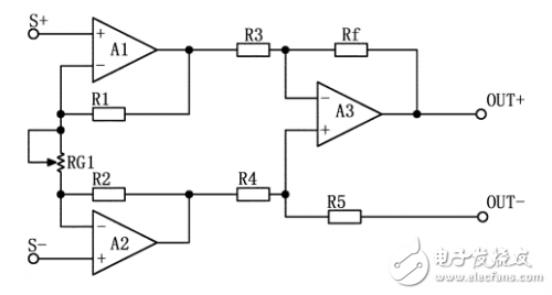
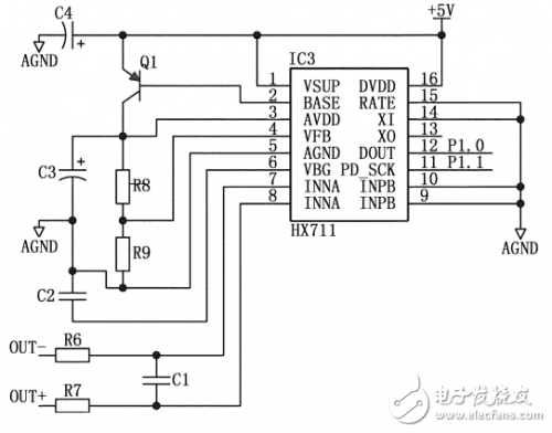
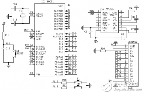
The digital display weighing instrument designed in this paper is based on the resistance strain sensor and the weighing control display system with the single chip as the control core. The measuring range is 0-10kg, the measuring accuracy is ±2g, the LCD screen displays the measurement data, and it can be multiple times. The measurement data is sent to the computer through the serial port. The system features high precision, stable performance and easy operation. The design diagram of the weighing instrument is shown in Figure 1: Figure 1 Weighing device design block diagram 1, hardware circuit design 1.1, load cell The resistance strain type load cell is composed of several main parts such as a strain gauge, an elastomer and a detection circuit. The elastic body is elastically deformed under the action of external force, so that the resistance strain gauge attached to the surface of the elastic body is also deformed along with it. After the resistance strain gauge is deformed, its resistance value will change (increase or decrease), and then corresponding measurement The circuit converts this resistance change into an electrical signal (voltage or current), thereby completing the process of converting an external force into an electrical signal. The detection circuit is shown in Fig. 2, and the resistance change of the strain gauge is converted into a voltage output. Because the Wheatstone bridge has many advantages, such as suppressing the influence of temperature changes, lateral force interference can be suppressed, and the compensation problem of the load cell can be solved conveniently, so the Wheatstone bridge is obtained in the load cell. A wide range of applications. Figure 2 Detection circuit composed of Wheatstone bridge The load cell generally has four input and output lines. The output resistance is generally 350Ω, 480Ω, 700Ω, and 1000Ω. The input terminal generally performs some temperature and sensitivity compensation. The input terminal resistance is 20~100Ω higher than the output end. The multimeter measures the resistance value to determine the input and output terminals. 1.2, the amplifier circuit The strain gauge load cell output signal amplitude is small (mV or even μV) and is often accompanied by large noise. For such signals, the first step in circuit processing is usually to first amplify the small signal with an instrumentation amplifier. The instrumentation amplifier circuit has better common mode rejection than a simple differential amplifier circuit. The main purpose of amplification is not the gain, but the signal-to-noise ratio of the circuit. In this design, the instrumentation amplifier adopts the structure of OP07 three op amps. As shown in Figure 3. When R1=R2, R3=R4, Rf=R5, the gain of the circuit is: G=(1+2R1/RG1)(Rf/R3). It can be seen from the formula that the adjustment of the circuit gain can be achieved by changing the resistance of RG1. Figure 3 meter amplifier circuit 1.3, A / D conversion circuit The A/D converter uses the electronic scale special chip HX711, which is a 24-bit A/D converter chip designed for high-precision electronic scales. Compared with other chips of the same type, the chip integrates peripheral circuits required by other chips of the same type, such as a regulated power supply and an on-chip clock oscillator. The input selector switch can be used to select either channel A or channel B to connect to its internal low noise programmable amplifier. Channel A has a programmable gain of 128 or 64, and the corresponding full-scale differential input signal amplitude is ±20mV or ±40mV, respectively. Channel B is a fixed 32-gain with a corresponding full-scale differential input voltage of ±80mV. Channel B is applied to system parameter detection including batteries. This design connects the instrumentation amplifier output to the channel A analog differential input as shown in Figure 4 below. Figure 4 HX711 application circuit 1.4, single chip and interface circuit The single-chip microcomputer adopts AT89C51 chip, and the circuit of the button, liquid crystal and computer interface is shown in Fig. 5. The HX711 serial communication line is connected to the P1.0 and P1.1 ports of the MCU. After being processed by the single chip microcomputer, the weighing data is sent to the liquid crystal display. At the same time, multiple measurement data is sent to the computer through the serial port. Figure 5 microcontroller interface circuit
China Integrated Smart Box,Communication Protection Box supplier & manufacturer, offer low price, high quality Communication Smart Box,Communication Protection Smart Box, etc.
Product Usage:
Integrated Smart Box,Communication Protection Box,Communication Smart Box,Communication Protection Smart Box Shenzhen Scodeno Technology Co.,Ltd , https://www.scodenonet.com


Safe City, Community Joint Defense, Skynet Project, Snow Bright Project, Sky Eye Project, Smart Transportation, High-speed Traffic Police, Community Joint Defense, Environmental Monitoring, Agricultural Monitoring, Oilfield Mining Area, Power Grid Line, River Monitoring, Communication Monitoring, Enterprise Unit, Scientific Research, Airport Station , Scenic parks, land monitoring, urban management monitoring, border monitoring, forest fire prevention, large areas and multiple complex environments requiring security protection, etc.
The intelligent surveillance box is a product independently developed to realize the intelligent management of the video surveillance system. It can ensure the security of video surveillance data transmission, and at the same time, it also effectively saves the later operation and maintenance management costs. It is a new generation of intelligent products .