We are the biggest Pressure Gauge Movement manufacture and supplier in China, we have more than 600 different types of Pressure Gauge movement and temperature movement, Include pressure gauge movement, Double decks movement, Temperature and pressure movement, Thermomanometer movement, Test gauge movement, capsule movement, Damping movement, Capsule system. Pressure Gauge Movement, Temperature Gauge Movement, Dial plate, bourdon tube, pointer, safety glass, connection Changshu Herun Import & Export Co.,Ltd , https://www.herunchina.com
Overview This application note discusses how to measure and improve return loss on DS317x and DS318x T3 / E3 transceivers: it first gives the definition of return loss, introduces the industry standard for return loss specifications; The measurement of loss is to first adopt the standard test settings, and then use the adjusted and improved settings; the final test data indicates that the proposed improvement scheme will result in a return loss that meets industry specifications.
This application note applies to the following products. T3 / E3 Transceivers ATM / Packet PHYs with
Built-In LIU DS3171 DS3181 DS3172 DS3182 DS3173 DS3183 DS3174 DS3184
Definition of return loss When a high-speed signal reaches the terminal of the transmission line, if the transmission line is not well terminated, part of the signal energy will be reflected toward the sending end. This reflected signal is mixed with the original signal, which will cause the original signal to be distorted, making it difficult for the LIU receiver to correctly recover the clock and data.
Return loss is the power ratio of the original signal to the reflected signal (expressed in dB). Simply put, the return loss indicates the relative size of the reflected signal, and also reflects the degree of matching or mismatch of the transmission line terminal. If the measured return loss of the LIU card is 20dB at a given frequency, it means that the reflected signal at this frequency is 20dB less than the original signal power.
Return loss requirements ITU G.703 and ETS 300-686 both specify the input return loss and output return loss requirements for E3 lines, as listed in Tables 1 and 2.
Table 1. Minimum return loss at the input Frequency Range (kHz) Return Loss (dB) 860 to 1720 12 1720 to 34368 18 34368 to 51550 14
Table 2. Minimum return loss at the output Frequency Range (kHz) Return Loss (dB) 860 to 1720 6 1720 to 51550 8
Measurement of Return Loss A.2.5 and A.2.6 in the ETS 300-686 specification describe the test configuration and procedures for measuring E3 return loss. The test setup shown in Figure 1 is used to measure the input return loss and verify that it meets the requirements listed in Table 1. The measurement setting of the output return loss is similar, except that the measurement setting is connected to the output of the transmitter rather than the input of the receiver.
In the setup of Figure 1, the return loss bridge uses Wide Band Engineering's A57TLSTD. Two 50Ω / 75Ω impedance converters (A65L from Wide Band Engineering) are used to connect the 75Ω bridge to the 50Ω signal generator and 50Ω spectrum analyzer port. The 75Ω precision resistor on the right side of the bridge in Figure 1 is part of the return loss bridge. Advantest's R3132 spectrum analyzer acts as both a signal generator and a spectrum analyzer. 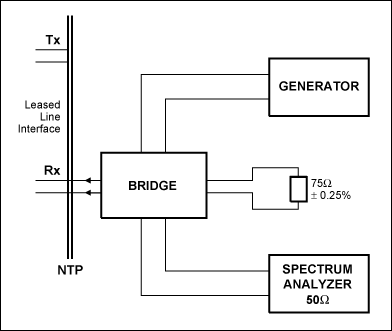
Figure 1. Return loss measurement setup
In the setup of Figure 1, the signal generator provides a sinusoidal signal with a peak value of 1V in the frequency range of 860kHz to 51,550kHz.
The test setup needs to be checked before measuring the return loss. The NTP interface of the bridge (the interface on the left in Figure 1) should be connected to a test load of 75Ω ± 0.25Ω. In Maxim's setup, this precision resistor comes from Wide Band Engineering as a component in the return loss bridge. When using this resistor as the test load, the return loss should be more than 20dB higher than the return loss required in Table 1. Figure 2 shows the return loss measured using the Maxim setting. At 1720kHz, the return loss measured by this setting is 45.27dB. 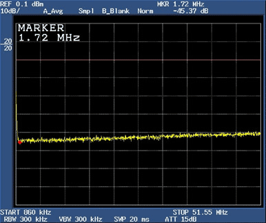
Figure 2. Return loss at 75Ω test load
When the NTP interface of the bridge is connected to the receiving port of the DS3174DK or DS3184DK evaluation board and a standard 330Ω termination resistor is used, the return loss measured at 34.37MHz is 16.86dB for DS3174 and 16.43dB for DS3184 Figures 3 and 4 show. These values ​​do not meet the requirements in Table 1. 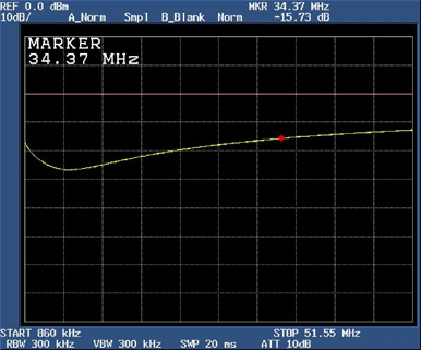
Figure 3. DS317x with termination network return loss at 34.37MHz 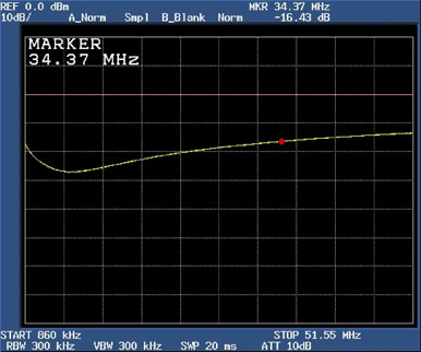
Figure 4. DS318x with terminating network return loss at 34.37MHz
Connect the NTP interface of the bridge to the receiving port of the DS3174DK or DS3184DK evaluation board, and use a standard 330Ω termination resistor. Figures 5 and 6 show the measured return loss at 51.55MHz. The DS3174 is 12.80dB and the DS3184 is 13.55dB. These return loss values ​​still cannot meet the requirements in Table 1.
Therefore, we clearly know that the return loss must be improved to meet the established requirements. 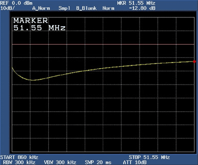
Figure 5. Return loss of DS317x with a terminated network at 51.55MHz 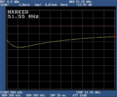
Figure 6. Return loss of DS318x with termination network at 51.55MHz
Improvement of the return loss of DS317x and DS318x We can improve the return loss by connecting a primary coil of 100nH inductor in series with LIU. The DS3174DK and DS3184DK evaluation boards have made this change. Figure 7 shows the standard termination network of the DS317x and DS318x receivers after this adjustment. 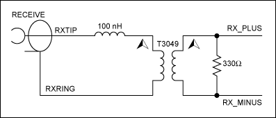
Figure 7. DS317x and DS318x LIU adjusted termination network.
Figure 8 shows that at a frequency of 34.37MHz, the DS317x with a 100nH inductance and a 330Ω termination resistor has a return loss of 21.65dB. Figure 9 shows that at a frequency of 34.37MHz, the return loss of the DS318x, which also has a 100nH inductance and a 330Ω termination resistor, is 22.16dB. Both of these return loss values ​​meet the requirements in Table 1. 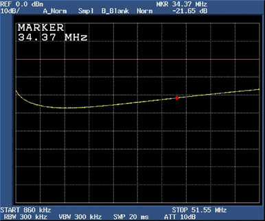
Figure 8. DS317x return loss at 34.37MHz after termination network adjustment 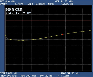
Figure 9. Return loss of DS318x at 34.37MHz after termination network adjustment
Figure 10 shows that at a frequency of 51.55MHz, the DS317x with a 100nH inductance and 330Ω termination resistance has a return loss of 16.85dB. Figure 11 shows that at a frequency of 51.55MHz, the return loss of the DS318x, which also has a 100nH inductance and a 330Ω termination resistor, is 15.49dB. Both of these return loss values ​​meet the requirements in Table 1. 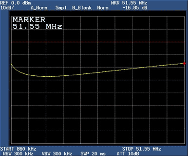
Figure 10. DS317x return loss at 51.55MHz after the termination network adjustment 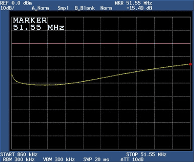
Figure 11. Return loss of DS318x at 51.55MHz after adjustment of the termination network
We are produce 7000 0000pcs of pressure gauge movement every year.
We also provide the pressure gauge accessories:
Pressure Gauge Case, include abs case, steel case, SS304 case, SS316 case
The window include acrylic window, glass window, safety glass window
The bourdon tube include brass bourdon tube, SS316L bourdon tube
The dial plate are alu dial plate, it can print all color and design for customize
The pointer have horizontal tail and fan tail.
Abstract: This application note discusses how to measure and improve return loss on DS317x and DS318x LIU transceivers. Improvements to standard test setups allow T3 / E3 transceivers and ATM / packet PHYs with built-in LIU to achieve return loss that meets industry standard specifications.