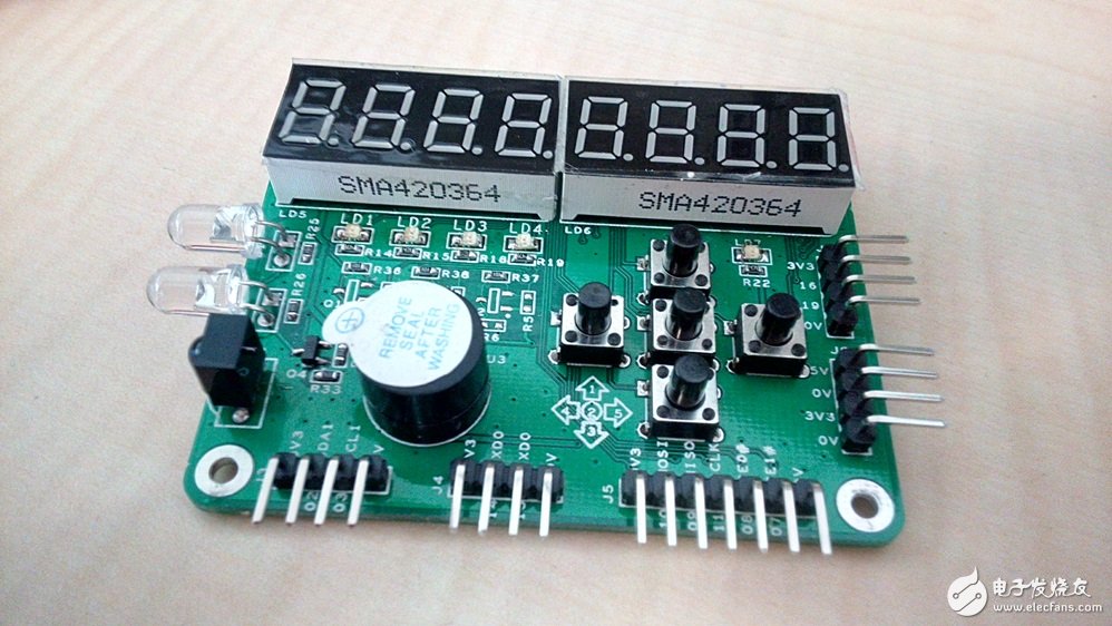
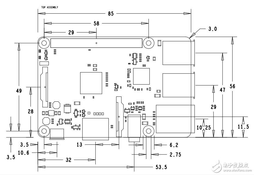
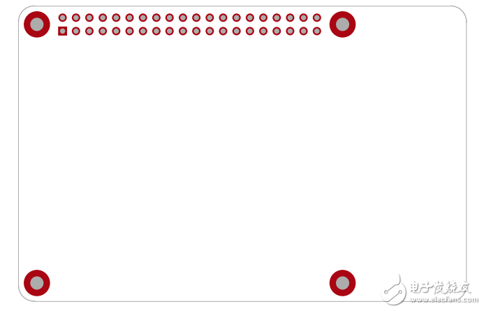
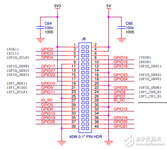
The Arduino expansion board is called Shield, and the Raspberry Pi expansion board is called HAT (Hardware Attached on Top), which means a hardware board attached to the top of the Raspberry Pi. Let's take a look at an open source Raspberry Pi expansion board from scratch, temporarily named Raspberry Pi ICA HAT. Raspberry Pi ICA HAT Demand analysis The original intention of designing HAT is to provide basic display and user input functions for Raspberry Pi, and to bring out hardware interfaces such as UART, I2C, SPI, etc., to easily connect other modules, and also as a user's entry board for learning Raspberry Pi hardware programming ( Starter Board). The configuration of ICA HAT is as follows: 1. User button x5, can be used as up, down, left and right and "OK" button; 2. User LED x4, to achieve basic indication function, and a power indicator LED; 3. Active buzzer x1, providing alarm function; 4. Infrared transmitting tube x2, infrared receiving head x1, realize infrared remote control function; 5. Seven-segment digital tube x2, realize 8-bit digital display, driven by MAX7219 chip with SPI interface; 6. I/O and power extensions are numbered. After setting the requirements, the first thing to consider is the structural problem. The design of this example is for the Raspberry Pi 2B model, and it is also compatible with the B+ model of the first generation. The picture below shows the mechanical structure of the Raspberry Pi 2B/B+: For the mechanical structure of the Raspberry Pi, both full length and half length HAT can be designed. The full-length board is the same size as the Raspberry Pi frame, but because the Raspberry's USB and RJ45 connectors are high, you need to be aware of whether the device at the bottom of the area will be in contact with the connector. The half-length board contains only four areas of screw holes. Both boards are connected to the header pins on the motherboard via a 2.54mm spacer and are secured to the motherboard by four M2.5 copper posts or screws. As shown below. Figure full length HAT and half length HAT The two sizes of HAT that have been designed have been stored on GitHub, and the reader can design on this basis. After analyzing the mechanical structure, the next thing to consider is the I/O resource allocation. The Raspberry Pi 2B/B+ I/O includes two SPI interfaces, two I2C interfaces, and a UART interface. There are no hardware PWMs and ADCs available. Also, I2C0 is used as the IDPROM interface for reading the HAT board information, which is not available to the user. SPI1 is also called SPI_AUX in the CPU. Currently, the Linux driver is not perfect, but it can be called through the pigpo library. As shown below: In this example, SPI0, I2C1, and UART0 are pulled out to the pin headers. The MAX7219 uses SPI1 control and uses GPIO as the chip select. Other functions assign GPIOs arbitrarily according to the wiring. Fiber Optic Accessories,Fiber Optic Cable Connectors,Fiber Optic Adapter,Fiber Cable Connectors Huizhou Fibercan Industrial Co.Ltd , https://www.fibercaniot.com


