A hand-held automobile engine tachometer is an instrument for detecting the instantaneous speed of an automobile engine. It generally includes two types of tachometers: a gasoline engine tachometer for measuring the speed of a gasoline engine and a diesel tachometer for measuring the speed of a diesel engine. The hand-held automobile engine tachometer has the characteristics of small size, light weight and convenient operation, and is widely used in automobile, engine production, research, maintenance and supervision and inspection departments. Since the detection principle and the use method of this type of engine tachometer are quite different from the conventional tachometer. The existing speed measurement standard device of the metrology department cannot verify its measurement accuracy. At present, the more commonly used verification methods are to compare it with other types of tachometers such as magnetoelectric or photoelectric. However, this comparison work needs to be performed on a dedicated engine test rig. This method can not meet the measurement requirements of the engine tachometer in terms of measurement range, measurement accuracy and stability, and it is difficult for the general measurement department to have such conditions. Therefore, it is necessary to develop a verification device to solve the problem of metrological verification of the hand-held engine tachometer. This article refers to the address: http://
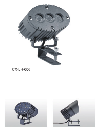
Led Tile Slots Lamp is commonly used in ancient architectural lighting, one light and one light, and the other side is the function of light casting.In addition, the luminaires can be equipped with a glare shield.The new energy-saving lamps with high power LED as the light source adopt optical grade PMMA high efficiency lens with low light loss and good illumination.The unique switching constant current source technology ensures that every LED works stably.It has good light transmittance, dust prevention and waterproof performance. The outer shell is made of aluminum alloy die casting parts for superconducting heat dissipation.Especially suitable for landscape architecture, ancient buildings, glazed tiles, villas, parks and other landscape decoration.The protection grade is up to IP65, which can adapt to various indoor and outdoor temperature and humidity environments.The color has the effect of red/yellow/blue/green/white/color change/full color etc.
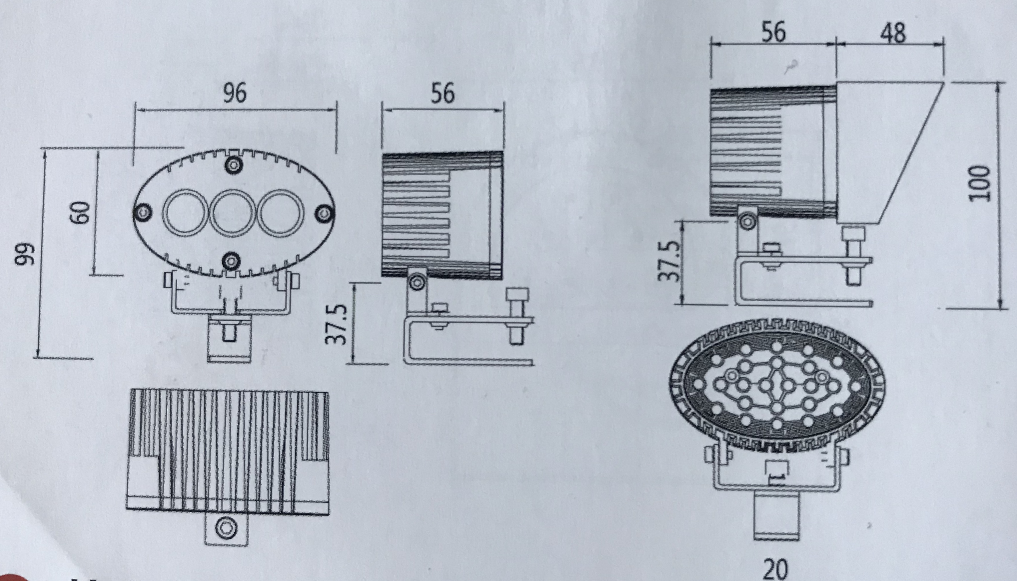
Product size
Led Tile Slots Lamp,Led Project Lamp,Led Night Lamp,Led Mood Lamp Jiangsu chengxu Electric Group Co., Ltd , http://www.chengxulighting.com
1 Measuring principle of hand-held car engine tachometer
1.1 Measurement principle of gasoline engine tachometer The gasoline engine of the car belongs to the ignition engine. It causes a change in the magnetic flux around the ignition coil and the high-voltage ignition wire in the ignition system of the engine due to the high-voltage discharge at each ignition. The electromagnetic coil in the gasoline engine tachometer sensor can sense this change and change the magnetic flux. Converted to a current pulse signal with the same frequency as the engine firing frequency. Gasoline engine tachometer sensors can be installed in a variety of ways: some are clamped on a high-voltage ignition line. Some use a suction cup to suck the sensor on the ignition coil: there is also a non-contact type, as long as the tachometer sensor is close to the engine ignition system. The ignition signal can be sensed. The gasoline engine tachometer can calculate the engine speed value by calculating the frequency value of the ignition pulse signal collected by the gasoline engine tachometer sensor and the stroke value of the measured engine and the cylinder value. The relationship between the gasoline engine speed value and the ignition pulse frequency is as follows:
N=3Okf/m
Where, IV is the rotational speed ignition pulse frequency displayed by the tachometer; the number of engine strokes: m is the number of engine cylinders.
1.2 Measurement principle of diesel engine tachometer The diesel engine tachometer clamps its sensor to the high pressure oil pipe of the first cylinder of diesel engine with a certain preload. Each time the engine injects oil, it will generate a high pressure in the high pressure oil pipe, and the high pressure oil pipe will slightly expand under the action of oil pressure. Squeeze the piezoelectric sensing element within the sensor. A piezoelectric charge is generated across the sensing element. Thereby, the injection pressure signal is converted into an electric pulse signal, and the electric pulse signal frequency value is equal to the injection frequency value of the first cylinder of the engine. The diesel engine tachometer can obtain the engine speed value by calculating the frequency value of the pulse signal collected by the sensor together with the measured number of engine strokes. Since the current automotive diesel engines are all 4-stroke engines, the hand-held automotive diesel engine tachometers are also designed for 4-stroke diesel engines. For this diesel tachometer, the conversion relationship between the speed of the diesel engine and the injection frequency is:
N=120f
In the formula, IV is the speed indicated by the tachometer; the factory is the injection frequency.
2 Measuring principle and composition of the verification device
2.1 Overall design scheme Due to the particularity of the above-mentioned hand-held engine tachometer detection principle. In order to verify it, the traditional speed measurement method such as mechanical standard speed device should be thrown away. Our solution is to design a low-voltage signal generating device to provide an accurate and stable low-voltage pulse signal whose frequency is equal to the gasoline engine ignition pulse frequency or diesel injection frequency corresponding to a certain standard speed. The low voltage pulse signal drives an ignition device or a pressure pulse generating device for simulating a signal required by the tachometer sensor. The ignition signal and the pressure pulse signal corresponding to the standard rotation speed are generated.
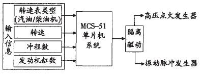
Based on the above ideas, we have developed a standard device for characterizing hand-held engine tachometers. The standard device consists of three parts: a low-voltage pulse signal generator, a high-voltage ignition generator for the calibration of a gasoline engine tachometer, and a vibration pulse generator for the calibration of a diesel engine tachometer (see Figure 1). 
Figure 1 verification device block diagram
2.2 Low-voltage pulse signal generator The working principle of the low-voltage pulse signal generator is shown in Figure 2. Its function is to generate a corresponding low voltage pulse signal according to the input tachometer related information and the set speed value. The frequency of the signal is equal to the high-voltage ignition pulse frequency or the injection frequency corresponding to the set speed value. To achieve this. We designed a device with MCS-51 series single-chip microcomputer as the main circuit. The timer interrupt function of the single-chip microcomputer is used to generate the voltage pulse signal. When the system works, first use the dial on the panel of the device to set the tachometer type (gasoline, diesel engine), engine cylinder number, stroke number, speed and other information. The MCU system reads this information first when it works. And through the operation to transform into the corresponding interrupt delay time. At the same time, the system starts timing. And output a pulse after the delay time arrives. Then repeat the process of "read input information, timing, output pulse". So cycle back and forth. A pulse signal of the corresponding frequency is generated. The pulse signal outputted by the single chip microcomputer system is sent to the high voltage ignition generator and the vibration pulse generator through the driving isolation circuit. 
Figure 2 low voltage pulse signal generator
2.3 High-voltage ignition generator The high-voltage ignition generator is used to generate the high-voltage ignition signal required for the calibration of the gasoline engine tachometer. It fully simulates the actual operation of the gasoline engine ignition system. It consists of an ignition amplifier, a high-voltage ignition coil and a spark plug (see Figure 3). The pulse signal from the low voltage pulse signal generator is first sent to the input of the ignition module. The drive switch circuit inside the ignition module causes the ignition coil primary coil to generate an on-off current. Further, a high voltage of several thousand volts is generated in the secondary coil and discharged through the spark plug to generate a high voltage discharge signal. All components that make up the high-voltage ignition generator use automotive finished electrical components.
In this way, on the one hand, the generated ignition pulse is close to the actual situation, and on the other hand, the installation of various gasoline engine tachometer sensors is also facilitated. ![]()
Figure 3 high voltage ignition generator
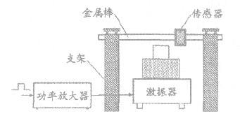
2.4 Vibration pulse generator The injection pressure pulse signal of the standard frequency required for the diesel engine tachometer is difficult to obtain by a simple method or device. We only have to find a way to replace the injection pressure pulse signal with other signals. Pass the test. We found that the diesel tachometer sensor was attached to a metal rod and tapped on the metal rod. The vibration of the metal rod also caused the piezoelectric element in the sensor to be squeezed. Thereby an electrical pulse signal is generated which is synchronized with the tap signal. Therefore, we can use mechanical vibration to strike the metal rod to simulate the injection pressure of the diesel engine, so that the diesel tachometer sensor can induce. To this end, we designed a vibration pulse generator. It consists of a small power amplifier, a vibration exciter, a fixed bracket, etc. (see Figure 4). The low voltage pulse signal from the low voltage pulse signal generator drives the exciter to generate mechanical vibration through the power amplifier. The metal hammer mounted on the exciter taps the metal of the fixed diesel tachometer sensor at the same frequency as the input voltage pulse. Rod. The metal rod generates a pulse vibration that simulates the injection pressure to induce the sensor. The purpose of verifying the diesel engine tachometer is achieved. 
Figure 4 diesel engine speed signal generator
3 Error Analysis The high-voltage ignition generator and pulse vibration generator in this metering device operate at a lower frequency. So as long as the installation and debugging is correct, there will be no misoperation. The resulting error can be ignored. The main factor affecting the accuracy and stability of the verification is the frequency error of the voltage pulse signal generated by the single-chip system. Since the metering device adopts a single-chip timer interrupt mode to generate a pulse signal. Therefore, the magnitude of the error is mainly determined by the conversion error that converts the input information into a delay time. As long as the program design is reasonable, the resulting verification error can be controlled to less than 0.1%.
4 Conclusion This verification device is suitable for testing various hand-held automobile engine tachometers. The calibration range is 100-9900r/min, and the accuracy is better than 0.1%. The verification device has been used for a period of time to achieve the desired effect. It mainly has the following characteristics:
(1) Taking into account the verification of two kinds of tachometers of gasoline engine and diesel engine, it has wide adaptability, high precision and easy operation. Reliable work;
(2) small size, simple structure, low cost and easy to manufacture;
(3) It has certain promotion value and can solve the problem of the measurement department's verification of the hand-held engine tachometer. 
