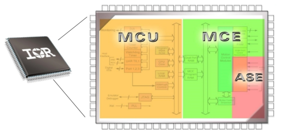
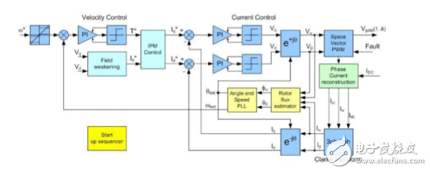
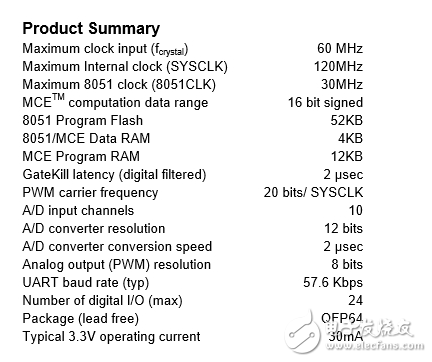
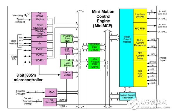
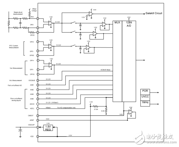
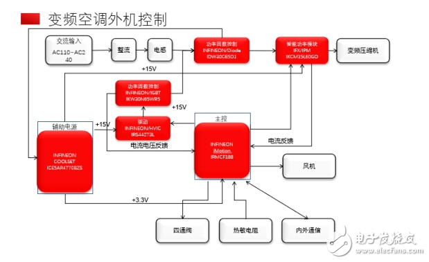
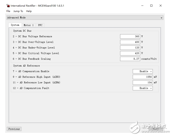
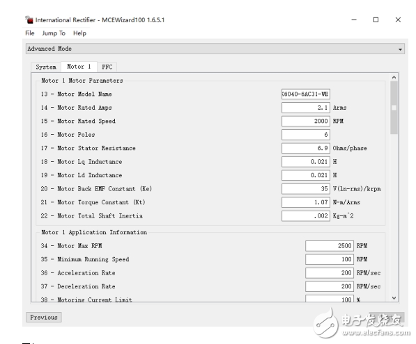
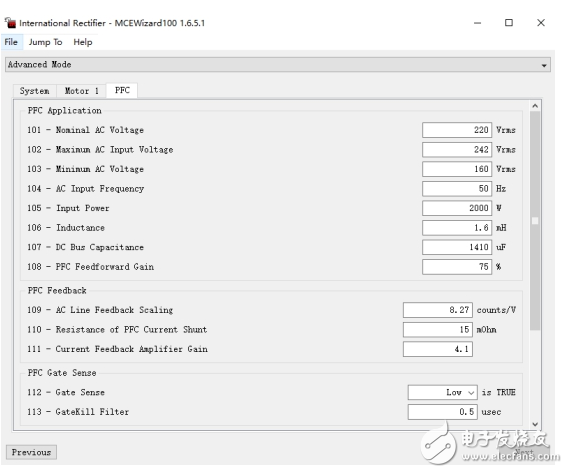
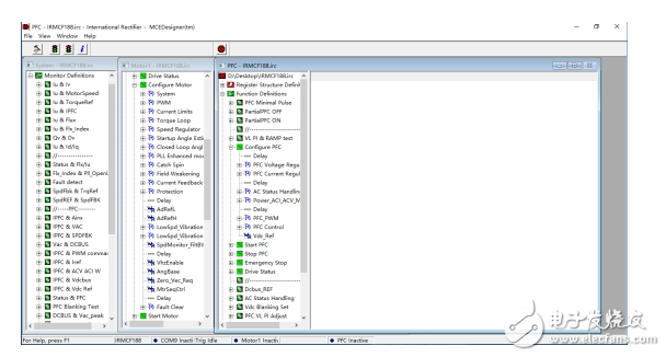
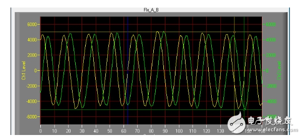
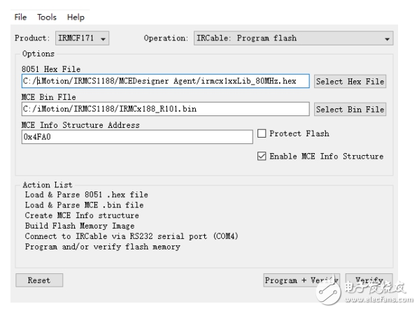
Preface With the improvement of people’s living standards, air conditioners have long entered people’s homes as a necessities of life. Compared with refrigerators and washing machines, each household generally only uses one, more and more families will install one set for each room. Air conditioners improve the quality of life, so the capacity of the air conditioner market is expected to reach several times that of the refrigerator and washing machine markets, and the prospects are very broad. In recent years, with the increasing maturity of inverter technology, the popularity of inverter air conditioners has gradually increased. In addition to the well-known energy-saving effect of inverter air conditioners, the advantages of soft air output, low noise, and resistance to air-conditioning diseases have also become more and more accepted by the public. It can be seen from the current situation of domestic and foreign air conditioner manufacturers’ shipments that inverters The proportion is higher than that of fixed frequency, and the growth momentum is unabated. In the future, the inverter design of air conditioners will become the mainstream of the market. At present, the air conditioner inverter solutions on the market are mainly divided into two types: Japanese and European and American. The Japanese system is dominated by Renesas and NEC solutions, while the European and American systems are represented by the TI solution and Infineon's iMotionTM solution that is highlighted today. The main difference between the iMotionTM solution and other solutions is that the iMotionTM solution is a dedicated motor drive solution. The chip has built-in a complete motor drive algorithm that has been verified by the market. Customers only need to concentrate on debugging and stabilizing the system and completing their own air conditioners. The main control program of the machine can quickly complete the development of the external machine and speed up the progress of the product to market. Introduction to iMotionTM Solution The hardware of the iMotionTM solution is based on Infineon's high-performance microprocessor. The processor is divided into two cores, MCE core and MCU core, as shown in Figure 1: Figure one Among them, MCE is the motor drive core, and all motor drive related work is completed by this part; ASE is a part of MCE, which mainly completes some signal processing and ADC work; The MCU part is an 8-bit MCU based on 51 cores, which is mainly used to configure the MCE and control other peripheral peripherals. For the motor control algorithm in the MCE core, Infineon has released different firmware programs according to different needs, which can be used directly under normal circumstances, and only need to complete the motor parameter configuration; for special needs, you can use Matlab to change the function , All the firmware released by Infineon company has corresponding Matlab file release, the user can change as needed, as shown in Figure 2: Figure II In view of the different applications of inverter air conditioners, Infineon has launched the "1PFC+1MOTOR" application IRMCF188 solution and the "1PFC+2MOTOR" application IRMCF311 solution, because the largest proportion in the market is the "1PFC+1MOTOR" control solution, so this article It focuses on the configuration and usage of the IRMCF188 solution. IRMCF188 chip introduction Figure three Figure 3 is the resource summary table of the IRMCF188 chip. It can be seen that the IRMCF188 chip has 64K Flash, 16K RAM, and TQFP64 package. This configuration can meet the current demand for MCU resources for most of the current air conditioners, and can complete the order of the inverter air conditioners. Application of chip scheme. The block diagram of the internal resources of the IRMCF188 chip is as shown in Figure 4: Figure Four It can be seen from the block diagram that the MCE part completes the drive and protection of the PFC, the drive and protection of the motor part, and the AD collection of various voltages and currents; the MCU part includes the peripheral resources required by the general-purpose MCU, and the two pass through dual-port RAM. To exchange data, this can ensure the timely and effective data exchange. In addition, it should be noted that the IRMCF188 chip contains a built-in high-speed operational amplifier and comparator, as shown in Figure 5. The advantage of this is that it can reduce the use of external components in the program, reduce the overall BOM cost, and shrink the printed board. The required area. It can be seen from the figure that the built-in operational amplifier and comparator can complete the single-resistor or double-resistance current sampling and protection of the motor, and the current sampling and AC voltage sampling of the PFC. It only needs to be configured through the external RC network. Appropriate parameters are sufficient. All these initialization tasks are all completed by part of the MCE firmware, and the user does not need to participate in the control at all. Figure 5 IRMCF188 Inverter Air Conditioner External Unit Application As shown in Figure 6 below, it is a block diagram of a standard inverter air conditioner outdoor unit. With AC fan and capillary tube, it can be applied to the three-level energy efficiency outdoor unit of 1.5P and below. Because the IRMCF188 control scheme is used, peripheral operational amplifiers and comparators can be omitted, and the entire structure is simple and clear, which is very conducive to product development and verification, and shortens the product listing cycle. Figure Six IRMCF188 motor parameter configuration Infineon has prepared detailed development documents and tools for iMotionTM motor control applications. The specific content can be downloaded from Infineon's official website, as shown in Figure 7. After installation, there are mainly three tools in the installation directory, which are used to configure, debug and burn iMotionTM chips. The following is a brief description of the three tools. Figure Seven MCEWizard100 This tool is used to configure motor parameters, mainly divided into three parts: system, motor, and PFC. The system page is shown in Figure 8. This page mainly configures the bus voltage and AD calibration information. Figure eight The motor page is shown in Figure 9. The input on this page mainly includes: Specifications provided by the compressor manufacturer, such as rated speed, resistance, inductance, back electromotive force, etc. The parameters of the relevant sampling circuit used on the circuit board, such as the resistance of the sampling resistor, circuit gain, etc. Current loop and speed loop parameters, such as current loop PI value, speed loop PI value, etc. This page is a key configuration page for whether the compressor can operate reliably and efficiently. After commissioning, some parameters need to be fine-tuned according to the performance of the whole machine system. Figure nine The PFC page is shown in Figure 10. The input on this page is mainly related to PFC parameters, such as input voltage range, inductance, capacitance, sampling circuit parameters, etc., which can be configured according to the final requirements of the air conditioning system. Figure 10 MCEDesigner The MCEDesigner tool is a powerful iMotionTM motor debugging tool that can import the configured motor parameters into the tool. Through the MECDesigner special program provided with the software by Infineon, you can start the evaluation of the motor and hardware system without any software development. And debugging, can completely replace the traditional software and hardware are probably ready to start evaluation and debugging mode, saving development time and reducing the risk of project establishment. The start interface of the MCEDesigner tool is shown in Figure 11. You can intuitively see all the parameters of the motor running. Some parameters can be changed in real time during the running of the motor, and you can directly see the changes in the running state of the motor to facilitate the determination of the parameters. Figure eleven The System column is an application similar to a software oscilloscope. It can send the selected variables to the computer screen in the form of waveforms, and intuitively judge the running status of the motor. It is particularly effective for variable analysis that cannot be directly measured by some oscilloscopes or logic analyzers. , As shown in Figure 12, shows the result of magnetic flux observation. This variable cannot be directly obtained by external measuring equipment. Figure 12 MCEProgrammer The MCEProgrammer tool is a dedicated programming tool for the iMotion series. It can download 8051 Hex files and MCE bin files to the chip for debugging. The interface is shown in Figure 13. Note that the two files must be programmed at the same time, otherwise the program cannot run normally. Figure 13 With the above tools, the evaluation and debugging of the PFC and compressor control of an inverter air conditioner external unit can be completed in the shortest time, and then only need to complete the design and development of the main control part (8051 part) program according to the requirements of the whole machine control. For the current era of frequent changes in air conditioners, the shortening of the development cycle will produce direct and considerable economic benefits in the market. to sum up The IRMCF188 chip is a special motor control chip launched by Infineon. With its high integration and simple development mode, it has incomparable technical advantages for the application of the inverter air conditioner 1PFC+1Motor, which can help customers in the shortest time. , Complete the design of the inverter air conditioner external unit at the optimal cost. Moreover, its built-in motor control algorithm has been accumulated for more than ten years, and it can fully meet the demanding requirements of the current inverter air conditioner market, and the risk of the program can be minimized. It is one of the preferred control solutions for the current inverter air conditioner outdoor unit. Author: Kris Burnon International Ltd. We make OBD connector with terminal by ourselves,
soldering type and crimping type are both available. Also 12V and 24V
type. OBD1, OB2, J1939, J1708, J1962, etc. Also molded by different
type, straight type or right-angle type. The OBD connector cables used
for Audi, Honda, Toyota, BWM, etc. We have wide range of materials
source , also we can support customers to make a customized one to
replace the original ones. Sae J1708 Connector,Sae J1939 Connector,OBD2 Diagnostic Connectors,Diagnostic Connector,Deutsch Diagnostic Connector ETOP WIREHARNESS LIMITED , https://www.etopwireharness.com