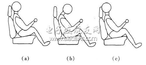
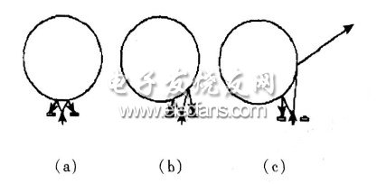
Aiming at the current severe fatigue driving behavior, a fatigue driving detection device was developed. Install an infrared emitting diode and two infrared receiving heads in front of the seat headrest directly in front of the driver's head. The current intensity of infrared emission is controlled by the single chip microcomputer, and the relative position of the head can be detected by detecting the information of the receiving head. . If the driver is in a fatigued driving state, the head must deviate from the normal position and the time exceeds the set value, then the alarm and brake control signals are output. The system has been tested on several typical vehicles to verify the correctness and effectiveness of the method, and it can achieve high measurement accuracy. 1 Structural characteristics of the detector If the driver is in a fatigued driving state, the head must deviate from the normal position and the time exceeds the set value, the device outputs an alarm and brake control signal. The reflective infrared sensor in the detector consists of an infrared emitting diode and two infrared receiving heads. The infrared emitting diode emits a modulated 38 kHz infrared beam and is installed on the seat headrest in front of the driver's head. The infrared emitting diode is placed in the middle, and the two infrared receiving heads are placed symmetrically on the left and right sides. 2 Driver head position analysis During driving, the driver's head position is different between normal and fatigue. The side view is shown in Figure 1. Figure 1 (a) shows that the driver's head position and seat headrest are normal when driving the car. A small distance of a few cm, instead of leaning on the headrest completely, because driving the eyes on the headrest will feel very uncomfortable and it is not convenient to observe the road conditions closer to the car. Figure 1 (b) shows the most common driving sleep posture when the driver is fatigued to drive the car, which is also the driver's initial fatigue sleep posture. At this time, the driver's head is generally greater than 15 cm from the seat headrest. In this case, it should be timely Alarm, if it lasts for 2 s, the braking system should be activated automatically. However, short-term other non-fatigue actions, such as leaning on the switch on the instrument panel, looking back and other short-term actions also have similar distance changes. At this time, it can be distinguished by time. The return to the normal position within 2 s is not regarded as fatigue driving judgment. Figure 1 (c) shows the driver's posture when he consciously took a short rest and closed his eyes while driving, but has not yet fallen asleep completely, but this is a prelude to completely asleep, with his head positioned close to the seat headrest, at a distance If it is 0, the alarm should be reported in time in this case, and it will evolve into the situation in Figure 1 (b). Figure 1 Side view of driver's head position Figure 2 is a top view of the driver's head, where the circle represents the driver's head, and the arrow represents the route of infrared emission and reflection. Figure 2 (a) is a schematic diagram of the relative position of the driver's head and the infrared sensor during normal driving. The infrared rays are emitted from the middle infrared emitting diode to the driver's head and are reflected back to the left and right infrared receiving heads. The distance traveled is basically equal. Figure 2 (b) shows the driver's head position after fatigue, which is skewed to the left or right. This is different from the typical position of Figure 1 (b). Converted to the position of Figure 1 (b), at this time the infrared sensor will detect different distances from left to right, and should also alarm or output a braking signal in time. Figure 2 (c) shows the position of the driver's head that continues to shift after fatigue. The infrared receiver on one side can no longer receive the reflected infrared light. The result of the infinite distance is obtained in the computer program, which shows that the driver The degree of fatigue is further strengthened, and alarms or braking signals should be output in time. Figure 2 Top view of the driver's head position Elliptical gear flowmeter (also known as displacement flowmeter and gear flowmeter) belongs to a kind of positive displacement flowmeter, which has high precision in flow instruments. It uses mechanical measuring elements to continuously divide the fluid into a single known volume part, and measures the total flow volume according to the number of times that the metering chamber fills and discharges the fluid in the volume part step by step and repeatedly. Oval gear flowmeter can be made of different materials (cast iron, cast steel, 304 stainless steel and 316 stainless steel). It is suitable for flow measurement in chemical industry, petroleum, medicine, electric power, metallurgy, food and other industrial departments. Ellipse Gear Flowmeter,Oval Gear Flow Meter,Gear Oval Flowmeter,Plastic Oval Gear Flowmeter Taizhou Jiabo Instrument Technology Co., Ltd. , https://www.jbcbyq.com
