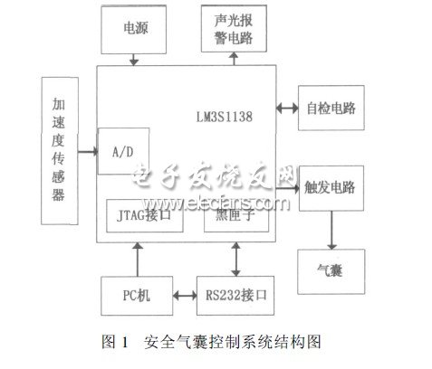
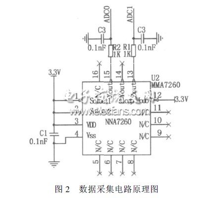
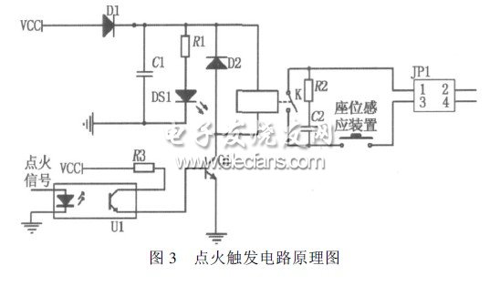
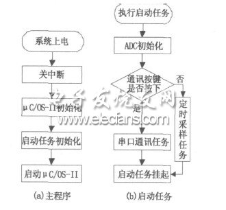
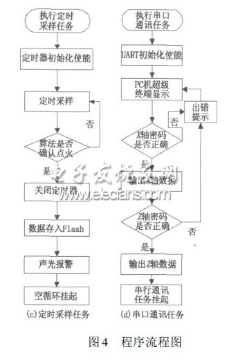
introduction With the popularity of cars and the acceleration of driving speed, the number of traffic accidents and casualties is also increasing year by year. In the event of a car collision, how to effectively protect the lives of drivers and occupants is an urgent problem to be solved. Airbags have become popular as passive protection devices used in conjunction with seat belts, and have become one of the main equipment for protecting passengers in automobile components. Airbag control system can be divided into three types: mechanical, analog electronic and embedded. For mechanical and analog electronic control systems, due to the limitations of hardware, flexibility is greatly restricted, and applications are increasingly reduced. The new generation of airbag control systems are all embedded control systems with microcontrollers. The control algorithm of the embedded control system is realized by software, which greatly improves the flexibility of the system, and has the functions of recording accident data and communicating with the host computer. The airbag of a car is required to be able to detect the occurrence of a car collision accident and control the detonation of the airbag in a very short time. In order to achieve the above goals, the microcontroller of the airbag control system requires strong computing power and sufficient I / O ports. Based on this, choose a high-performance 32-bit microcontroller, research and develop a more practical automotive airbag control system, has certain application and reference value. Based on the research of advanced control systems at home and abroad, this paper puts forward the design plan of the automobile airbag control system based on the ARMCortexM3 core 32-bit microcontroller, and carried out trolley and real vehicle tests respectively. 1 ARMCortexM3 core and microcontroller LM3S1138 ARM has developed a 32-bit CortexM3 core processor for low-cost applications. The processor effectively uses chip space, highly integrated peripherals, and the core to form a system on chip (SoC). The ARMCortexM3 processor incorporates Thumb2 instruction 32-bit Harvard microarchitecture. Thumb2 technology improves code density, reduces memory usage by 26% compared to 32-bit encoding, and improves performance by 25% compared to 16-bit encoding. By lowering the clock frequency, providing lower power consumption, reducing R & D costs and improving enterprise efficiency. Tail-Chaining interrupt technology is implemented on the chip, which reduces the delay between interrupts to 6 machine cycles, which can reduce interrupts by 70% in practical applications. The microprocessor of this system selects LM3S1138 industrial grade microcontroller based on ARMCortexM3 core of TI company. Its operating temperature range is -40 ~ 85 ° C, and has good electromagnetic compatibility characteristics, can be used in the field of automotive electronics. 2 System working principle and design 2.1 The working principle of the system The airbag control system is mainly composed of sensors, self-check circuit, trigger circuit, communication circuit and alarm circuit, as shown in Figure 1. Its working principle is: after power on, the system performs self-check to determine whether the trigger circuit can work normally. If there is a fault in the trigger circuit, the alarm circuit performs an audible and visual alarm, indicating that the system is not working properly and informs the driver to repair it in time. When the self-test is normal, the signal measured by the acceleration sensor MMA7260 is continuously sampled by the 32-bit microprocessor LM3S1138. When the car is subjected to a high-speed collision within a certain angle, the system immediately triggers the igniter in the airbag package after algorithm analysis and confirmation. The airbag is quickly filled with gas to block the possible collision between the driver and the car components. The throttle damping effect of the air hole buffers and absorbs the driver's kinetic energy, so as to achieve the purpose of protecting the driver's safety. 2.2 System hardware design 2.2.1 Acceleration measurement circuit This article selects Freescale's silicon capacitive acceleration sensor MMA7260. It has signal amplification conditioning, low-pass filtering and compensation functions. The device's zero acceleration bias, full-scale range, and filtering characteristics are all set by the manufacturer, and no external passive components are required. Due to the high integration and reliability of the sensor manufacturing process, the interference from the outside world is minimized. MMA7260 directly adopts IC integrated package, which can be directly soldered on the PCB board, which is convenient for debugging. The LM3S1138 processor has a built-in 8-channel 10-bit ADC with a sampling rate of up to 1M / s, which is accurate enough for airbags. After the acceleration is measured by the sensor, the voltage value is output from the corresponding output pin. The voltage value is analog-to-digital converted by the ADC built in the LM3S1138 processor, and then stored in the array set by the software. The hardware schematic of the acceleration measurement circuit is shown in Figure 2. This system only uses the X and Z axes of the MMA7260 three-axis acceleration sensor to judge the collision in the horizontal direction. The X-axis direction measures the acceleration of the frontal collision of the car, and the Z-axis direction measures the acceleration of the vehicle in the vertical direction. When a car drives over a ditch or rough road at high speed, it will cause the sensor to generate a large signal even if there is no collision. This signal is superimposed on the collision waveform of a low-speed collision, causing the microcontroller to mistake it for a high-speed collision, which in turn causes a false detonation. In view of this, when the car Z axis (vertical direction). When a large acceleration is generated, the airbag is designed not to detonate regardless of the acceleration in the X-axis direction. It avoids unnecessary losses caused by the detonation of the airbag when the car passes the ground barrier at high speed, and enhances the anti-interference performance of the road surface. 2.2.2 Ignition trigger circuit Because the ignition of the airbag gas generator needs 20mA current pulse. If the I / O port of the LM3S1138 is used to output a high level for detonation, the drive is too small to meet the requirements. The system uses electromagnetic relays, which can drive high-power loads under the control of the LM3S1138 output port. Because the relay will produce more obvious interference, an anti-interference circuit is added around the relay and used in conjunction with the optocoupler to make the processor photoelectrically isolated from the trigger circuit. When a collision occurs, the airbag not only has no protective effect on adults or children who are too short, but the huge impact of the detonation will even kill it. In order to better achieve safe ignition and intelligent ignition, the system sets a seat pressure sensing device on the trigger circuit. If an adult is seated, the device is closed and the ignition circuit can work normally. On the contrary, if the device is disconnected, it means that no one is seated or only a small adult or child is seated, and the trigger circuit cannot form a loop. At this time, even if the car collides and the algorithm issues an ignition signal, the airbag does not explode. In this way, it not only prevents the economic loss caused by detonating the airbag when no one is seated, but also avoids the damage caused by the airbag to short adults and children. The principle diagram of the ignition trigger circuit is shown in Figure 3. 2.3 Software design of the system The system uses CortexM3 core processor to simplify the software development environment. For a series of microcontrollers such as LM3S1138, TI officially provides free C-based language (in line with ANSIC standards). The driver library, which contains many firmware function libraries, has corresponding routines for each peripheral, which can be easily modified and transplanted according to application needs. Therefore, in the software programming, the software management of the assembler is not necessary, and the driver library C language function can be used for programming and development. When developing application programs, the routine design of the driver library is used for modular design. Not only is the program easy to write, but the code is concise and readable. For writing large programs, the use of driver libraries can enhance reliability and security, while reducing maintenance costs. Therefore, the system software program uses the driver library routines provided by TI to carry out modular programming, divide the entire system program into several small programs or modules, and independently design, program, and test. Finally, build a complete project of each module to complete the application design. The whole project is divided into four modules: main program, start task, timing sampling task and serial communication task. The flow chart is shown in Figure 4. Solar Charging Controller,Charge Controller,Solar Controller,Solar Regulator SUZHOU DEVELPOWER ENERGY EQUIPMENT CO.,LTD , https://www.fisoph-power.com