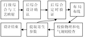
Design and Implementation of Ethernet Controller Chip Network controller chip function and design Figure 1 Functional block diagram of the Ethernet controller chip Figure 2 State transition diagram of the sending module Figure 3 Receiver module state transition diagram Figure 4 Functional simulation of the core module Design Verification This paper presents the verification process of core functions. Connect these core functional modules into a loop (the sending module is directly connected to the receiving module), the sending module sends out data packets according to the 802.3 protocol, the receiving module processes these data packets according to the 802.3 protocol, and the data packets that meet the requirements are sent to (receiving buffer) Area), the functional simulation waveforms of these modules in Mentor's ModelsimSe5.8 are shown in Figure 5. Figure 5 chip implementation process After the design verification of the chip is passed, the layout of the entire chip is obtained through the process shown in FIG. 5.
All in one pc is a new trend for desktop type computer nowadays. What you can see at this store is Custom All In One PC. There are 19 inch all in one pc, 21.5 All In One PC, All In One PC 23.8 Inch and 27 inch all in one pc, which are the main sizes at the market. How to choose the most suitable one for special application? According to clients` feedback, 19.1 inch entry level, 21.5 inch middle and low level, 23.8 or 27 inch higher level-All In One PC I7. Some clients may worry the heat-releasing since equipped releasing fan into the back of monitor, see no releasing fences on back cover. However, totally no need worry that point, cause special back cover material and releasing holes can meet the demand of heat releasing.
You can see All In One Business Computer, All In One Gaming PC, and All In One Desktop Touch Screen series at this shop.
Any other unique design or parameters, just feel free to contact us so that can get right and value information quickly.
Believe will try our best to support you!
All In One PC,All In One Pc I7,Custom All In One Pc,All In One Pc 23.8 Inch,21.5 All In One Pc Henan Shuyi Electronics Co., Ltd. , https://www.sycustomelectronics.com
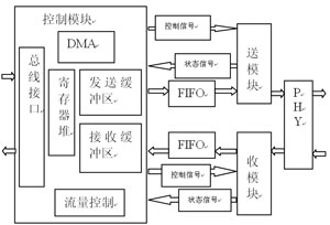
The IEEE 802.3 protocol is defined for the transmission medium physical layer (PHY) and medium access control protocol (MAC, Media Access Control) of the Ethernet CSMA / CD standard. The chip is composed of PHY, sending module, receiving module, FIFO, and control module. The control module includes register file, DMA (Direct Memory Access) module, flow control module, receiving buffer and sending buffer. The functional block diagram of the network controller chip is shown in Figure 1. 
1 IEEE 802.3 Ethernet MAC data frame structure When sending data, the sending module automatically adds a 7-byte preamble and a 1-byte frame start delimiter before the data to be transmitted, followed by a 6-byte The destination address and the source address of 6 bytes, then the length / type is 2 bytes, followed by the data area, and then 46 to 1500 bytes of data. If the data length is less than the minimum length of 46 bytes when sending, the sending module automatically fills to reach the minimum length, and finally the 4-byte cyclic redundancy check code.
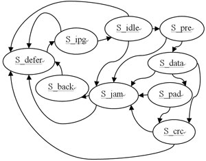
2 Sending module The function of sending module is to send data packets according to CSMA / CD protocol. The sending module state machine controls and coordinates the timing of each sending submodule. The sending module state machine is shown in Figure 2. 
The S_defer state indicates that the network is busy. If the network is idle, the network idle state S_idle is entered after the minimum frame gap time. If you need to send a data packet, send it through S_pre, S_data, S_pad, S_crc and other states. If a conflict signal is detected, it will enter the S_jam state. In the S_jam state, determine whether it is local collision or late collision. If it is local collision, enter the S_back state, and retransmit the current data frame according to the backoff algorithm, otherwise directly enter the network busy state, and give up the frame.
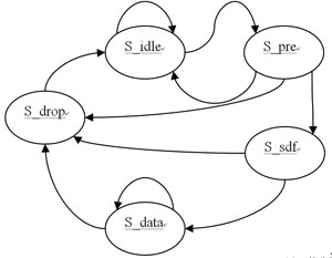
3 Receiver module The task of the receiver module is to receive data frames. The physical interface transceiver PHY turns the received network data into binary data and sends it to the receiving module. The receiving module sends the correct data to the receiving buffer through the control of the receiving FIFO and DMA. The function of the receiving module also includes removing the preamble / frame separator of the received frame; comparing the destination address to determine whether to discard the current data frame; performing CRC check on the received data packet to determine whether the data is in error during transmission. The receiving module state machine is the core of the receiving module, which controls and coordinates the work and timing of each sub-module of the receiving module. The state machine of the receiving module is shown in Figure 3. 
After reset, the state machine enters the S_idle state. If the data is invalid, it stays in the S_idle state, otherwise it enters the S_pre state. The role of S_pre state and S_sdf state is to remove the preamble and frame interval character. When all the frame interval characters are detected, enter the S_data state, use the byte counter in the S_data state, record the number of bytes of the received data, and compare the destination address. If the destination address matches, the received data is written to the receive FIFO, otherwise the frame is discarded and not written to the FIFO. The byte counter also determines whether the received data packet exceeds the maximum length of the frame. If the data valid signal is invalid in the S_pre state, S_sdf state or S_data state, all enter the S_drop state. 
4 Control module The control module includes DMA (direct memory access) module, flow control module, buffer module, register file module and bus interface module. The function of the DMA module is to carry the data of the receiving FIFO to the receiving buffer, and the data of the sending buffer to the sending FIFO. The frame is dropped when the port of the flow control module is blocked. This method is achieved when the receive buffer begins to overflow by sending the blocking signal back to the source address. Flow control can effectively prevent the impact of a large amount of data in the network on the network, and ensure that the user network operates efficiently and stably. There are two ways to control the flow: (1) In half-duplex mode, flow control is achieved by backpressure, which is what we usually call backpressure counting. This counting is done by sending jamming signals to the sending source Make the information source reduce the sending speed. (2) In full-duplex mode, flow control generally follows the IEEE 802.3X standard. The switch sends a "pause" frame to the information source to suspend its transmission. The buffer module consists of a 32KB SRAM, which is divided into a receiving buffer and a sending buffer. The size of the receiving buffer and the sending buffer can be determined by user programming. The buffer is managed by paging, 256B is a page. The host exchanges data with the chip through the bus interface, and controls the work of the chip by reading and writing the register file. 
In the figure, clk is the system clock; rst is the reset signal; tx_req is the send FIFO request signal, so that the DMA carries the data from the send buffer to the send FIFO; tx_fifo_data_out is the 8 data from the send FIFO, the send module encapsulates these data, and sends To the PHY; there is no verification of the PHY, the data TXD and data enable TXEN sent by the sending module are directly connected to the data terminal of the receiving module and the data valid signal respectively; the receiving module performs serial-to-parallel conversion of the TXD, and 8 is rx_data; byte_cnt is the number of rx_data received.
After the functional simulation is passed, the core modules are connected into a whole (SRAM directly calls the Quartus II IP Core), and after the Quartus II synthesis, it is downloaded to the FPGA development board. Use FPGA to simulate the network controller chip and communicate with the computer. FPGA and PC are connected through RJ-45. The application software sends a data packet to the FPGA. After receiving the data packet, the receiving module transfers the data from the FIFO to the receiving buffer through DMA. After the reception of a packet of data is completed, the FPGA sends out the data packet just received through the additional logic. The additional logic also completes the function of inverting the received data bit by bit. The application software displays the data packets received by the PC. By comparing the data packets sent from the PC to the FPGA and the data packets sent from the FPGA to the PC, it is verified that the core module functions correctly (the additional logic of the FPGA performs bit-by-bit on the received data packet Invert operation).
This tape-out adopts Hua Hong NEC 0.35μm CMOS process, the chip area is 5640μm × 5480μm (without planning the slot and buffer zone), the chip has 100 pins. The upper right part of the chip is the digital area that implements the MAC layer. The lower left area is the IP Core--32KB SRAM provided by Hua Hong NEC. It is used as a buffer. The lower right area completes the PHY function and is surrounded by pins.